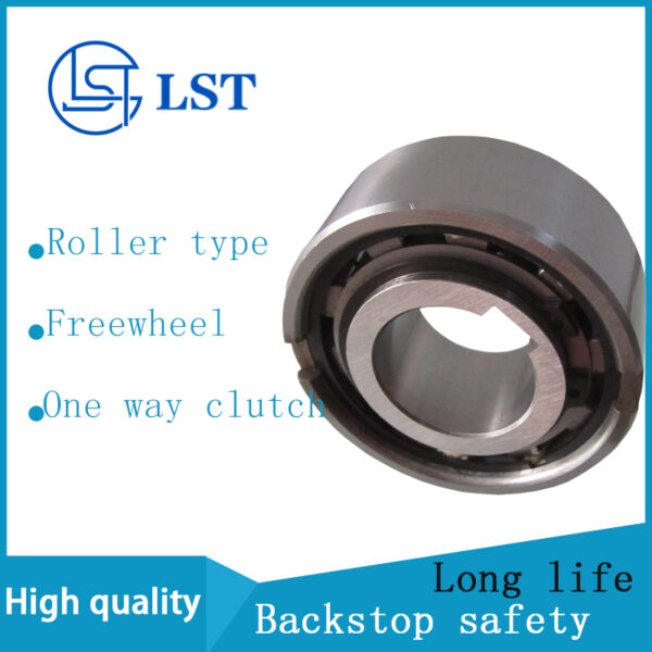
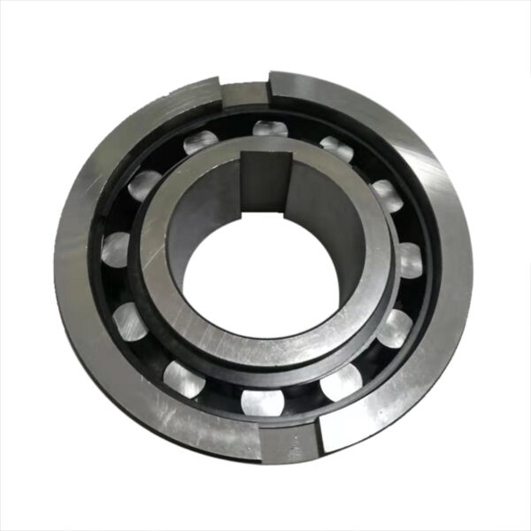
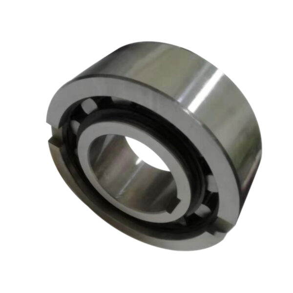
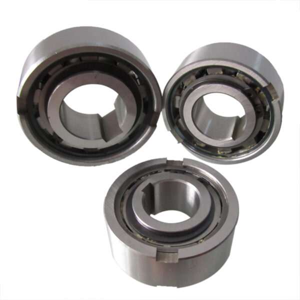
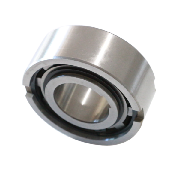
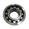
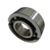
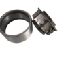
ASNU40 One Way Clutch Ratchet Type Clutch
Engineered ASNU40 one way clutch ratchet type clutch for overrunning, backstopping, and indexing operations. High torque transfer, DIN 6885.1 keyway, and precision raceways.
ASNU40 One Way Clutch Ratchet Type Clutch: Precision Torque Transfer & Directional Drive Systems
The ASNU40 one way clutch ratchet type clutch manufactured by LST Sprag Clutch delivers robust non-return mechanical power transmission across demanding powertrain, material handling, and industrial manufacturing installations. As an integrated one way freewheel bearing engineering solution, the ASNU40 configuration operates as a heavy-duty directional drive clutch, eliminating reverse slippage while ensuring minimal parasitic drag during free mechanical rotation.
1. Product Overview & Structural Architecture
The ASNU series represents an industry-standard, bearing-supported roller ramp clutch topology designed for multi-regime deployment: overrunning, indexing, and backstopping. While traditional drive engineers often colloquially specify a ratchet and pawl mechanism for unidirectional control, positive-locking ratchet assemblies induce substantial cyclic shock, localized tooth wear, and audible acoustic emission. The modern ASNU40 one way clutch ratchet type clutch engineered by LST Sprag Clutch replaces legacy stepped pawls with precision-ground, hardened alloy ramps and cylindrical rollers supported by spring-energized contact geometries. This achieves instantaneous, zero-backlash engagement without the destructive impact forces common to kinematic ratchet devices.
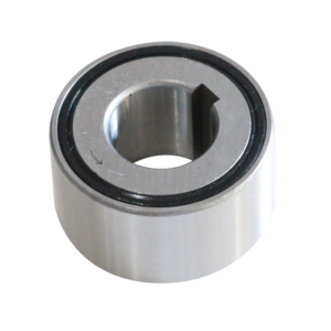
Structurally, the unit combines an inner outer race freewheel assembly dimensioned with a 40 mm nominal bore size. The inner race incorporates a standard keyway to DIN 6885.1 for positive keyed transmission to the drive shaft, while the outer race features an interference fit with side snap-ring retention grooves designed to mount directly into standard bearing housing bores (matching external dimensions of the 63.. series ball bearings). Internal rolling elements operate under hydrodynamic or boundary oil/grease lubrication films, providing smooth transition from high-torque lock-up to unrestricted mechanical overrun.
Key Structural Attributes of the LST Sprag Clutch ASNU40 Series:
- Dual-Track Raceway Design: High-carbon chromium bearing steel (GCr15 / 100Cr6) heat-treated to 60–62 HRC for superior subsurface shear strength.
- Independent Spring Tensioning: Individual leaf or coil springs behind each roller element ensure instantaneous lockup wedging regardless of rotational acceleration rates.
- Direct Integration Compatibility: Dimensional envelope mirrors standard metric deep groove ball bearing configurations to streamline machinery retrofits and housing machining.
2. Industrial Operational Pain Points & Technical Solutions
Selecting the appropriate mechanical overrun mechanism dictates equipment uptime, maintenance cycles, and operator safety. Plant managers, reliability engineers, and drive designers frequently encounter critical mechanical failures when applying standard couplings or sub-optimized ratchet fixtures:
Mechanical Backlash and Tooth Shearing in Ratchets
Conventional mechanical ratchet stops rely on geometric catch points separated by discrete pitch angles (often 5° to 15°). Under severe reverse torque spikes—such as bucket elevators or inclined conveyor rollbacks—this angular travel allows kinetic momentum to build before engagement, causing pawl fracture and violent dynamic failure. The ASNU40 functions as a stepless anti reverse rotation device; its internal rollers maintain continuous contact with internal ramps, locking up instantaneously (0.00° theoretical backlash) upon directional reversal.
High Parasitic Drag and Thermal Generation During Freewheeling
Continuous high-speed overrun creates sliding friction, premature oil degradation, and thermal seizure if rollers or sprags do not achieve stable hydrodynamic lift-off or consistent hydrodynamic fluid film maintenance. LST Sprag Clutch calibrates the internal ramp profiles and surface micro-topography (Ra ≤ 0.2 µm) of the ASNU40 to minimize friction-induced heat, prolonging continuous-run operational life during protracted overrunning cycles.
Shaft Misalignment and Housing Deformation Stress
In flexible industrial drive trains, axial float and micro-radial misalignments translate into eccentric loading across sprag or roller cages. Because the outer diameter of the ASNU40 matches standard bearing tolerances, plant builders can integrate secondary support bearings within the same continuous bore, preventing localized stress concentrations and cage failure.
3. Kinematic & Mechanical Design Principles
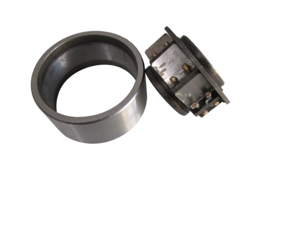
The ASNU40 operates on the wedge-ramp principle. Unlike a purely frictional friction disk or an intermittent sprag type one way clutch that uses asymmetrical figure-eight sprags, the ASNU40 employs precision cylindrical rollers seated between flat internal ramps machined into the inner race and a perfectly cylindrical outer raceway track.
Engagement Dynamic (Torque Transfer Mode)
When the inner race rotates relative to the outer race in the driving direction (or when the outer race attempts to reverse against a locked inner race), the individual rollers are forced upward into the narrowing convergent wedge zones formed by the ramp angles. Individual energizing springs ensure every roller maintains zero-clearance tangential contact with both races simultaneously. As torque increases, normal force scales proportionally, creating a compressive lock that transmits mechanical energy with zero slip. The high surface hardness ensures that elastic deformation remains strictly within the calculated Hertzian contact stress threshold.
Disengagement Dynamic (Overrunning Freewheel Clutch Mode)
When the driven shaft speed exceeds the driver speed, or the drive reverses direction, the relative tangential velocity drives the cylindrical rollers backward down the ramp incline into the broader clearance chamber. The clamping pressure vanishes instantly. The rollers then rotate smoothly about their own axes within the fluid lubricant layer, establishing an unhindered mechanical overrun mechanism with minimal drag torque.
Indexing Freewheel Action
In reciprocating conversion drives—such as packaging feed rolls, punch press indexing, or textile metering—the indexing freewheel clutch mode converts linear or oscillating reciprocating strokes (via pneumatic cylinders or linkages) into precise, incremental unidirectional rotary motion. The fast response time of the spring-actuated rollers in the ASNU40 allows for high cyclic indexing frequencies without step drift.
4. Core Functional Operating Modes: Technical Analysis
Industrial drives demand rigorous classification of the freewheel function. Specifying the ASNU40 requires analyzing which race rotates, which overruns, and the thermal profile developed across operating shifts:
A. Overrunning Mode
Commonly implemented in dual-motor drives (e.g., main production motor combined with an auxiliary creeping/inching drive). When the high-power main motor activates, the ASNU40 disengages the auxiliary gear train automatically, preventing mechanical back-driving and catastrophic motor overspeed without requiring electrical interlocks or clutches.
B. Backstopping Mode (Backstop Clutch Bearing)
Installed as a non return bearing clutch on inclined conveyors, elevators, and pump systems. The outer race is grounded to the stationary machinery frame, while the inner race is keyed to the shaft. Continuous forward rotation proceeds unimpeded. The microsecond the drive cuts out, gravity-induced reverse rotation engages the roller ramps, locking the load securely in place and functioning as a fail-safe mechanical brake.
C. Indexing Mode
Applied in automated assembly tables and paper-converting machinery. One race oscillates back and forth through a set angular displacement. The companion race advances solely during the stroke phase and remains stationary during the return stroke, delivering accurate material advance per cycle.
5. Specialized Industrial Application Sectors
The ASNU40 is deployed globally across heavy engineering sectors where drive continuity, machine integrity, and operator protection are non-negotiable:
- Mining & Bulk Material Handling: Integrated into drive pulley shafts for inclined belts, bucket elevators, and ball mill auxiliary turning gear where an anti reverse rotation device is critical to safeguard against material rollback under full load.
- Agricultural & Forestry Machinery: Applied in high-inertia cutting rotors, round balers, and flail mowers. When the tractor PTO decouples, the ASNU40 acts as a continuous overrunning freewheel clutch, allowing the high-inertia cutter drum to coast down safely without reverse-torquing the tractor transmission.
- Industrial Ventilation & Fluid Handling: Positioned in dual-fan configurations and multi-pump manifolds to eliminate reverse airflow or fluid back-spinning through unpowered parallel units.
- Printing, Converting & Packaging Automation: Utilized as a high-precision torque transfer clutch and web tensioner feed unit for indexing rolls and rotary labeling turrets.
- Automotive & Commercial Vehicle Transmissions: Integrated into auxiliary hybrid drives, starter-generator decouplers, and specialized heavy transmission assemblies to decouple secondary kinetic systems.
6. ASNU40 Technical Specification & Dimension Matrix
The following technical parameters outline engineering performance indicators for the standard ASNU40 model series. Confirm operational torque, overrunning speed, and dynamic radial loads against your mechanical design envelope.
| Engineering Parameter | Designation / Value | Unit / Standard |
|---|---|---|
| Nominal Bore Diameter (d) | 40 | mm |
| Outer Diameter (D) | 90 | mm (-0.015 / -0.035 tolerance) |
| Overall Width (B) | 33 | mm (ISO standard series) |
| Inner Race Keyway Dimensions | 12 x 3.3 | DIN 6885.1 standard |
| Nominal Transmissible Torque (TKN) | 840 | Nm |
| Maximum Peak Torque (TMAX) | 1,680 | Nm |
| Max Inner Race Overrunning Speed | 1,800 | RPM |
| Max Outer Race Overrunning Speed | 1,200 | RPM |
| Raceway Material | 100Cr6 (AISI 52100) | Case/Through-hardened 60-62 HRC |
| Estimated Weight | 1.30 | kg |
*Note: The ASNU40 is non-self-bearing. Adjacent bearing support is required to maintain axial and radial concentricity between inner and outer races.
7. Engineering Installation, Lubrication & Maintenance Protocols
To maximize the service life of an ASNU40 one way clutch ratchet type clutch, mechanical engineers and maintenance personnel must follow specific handling, fit, and lubrication guidelines:
Machining Tolerances and Housing Press-Fit
The ASNU40 outer race is designed for an interference press fit into a rigid housing bore machined to K6 or H7 tolerance. Ensure pressing forces are applied strictly against the face of the outer race using a dedicated mounting sleeve; never transmit mounting force through the internal rolling elements. Shaft tolerance beneath the inner race should strictly follow h6 or j6 to preserve dimensional integrity and avoid binding the roller ramp tracks.
External Bearing Support Requirement
Because ASNU series units do not integrate internal bearing balls to locate the races coaxially, precision deep groove or cylindrical roller bearings must be mounted directly adjacent to the freewheel. Maintain radial runout below 0.03 mm to preserve uniform roller clearance and prevent irregular wedge lockup.
Lubrication Selection Criteria
Proper lubrication governs operational friction and heat dissipation. The clutch can be lubricated via splash oil, circulating pressure oil, or dedicated industrial grease:
- Oil Lubrication: Recommended for medium-to-high speed overrunning. Use industrial gear oils or automatic transmission fluids (ATF) with kinematic viscosity between ISO VG 32 and VG 68. Warning: Never use oils containing solid friction modifiers, such as Graphite or Molybdenum Disulfide (MoS2), as they reduce the friction coefficient below the wedge angle lockup requirement, resulting in fatal slip under load.
- Grease Lubrication: Preferred for low-speed backstopping, indexing duties, or vertically positioned shafts where oil retention is challenging. Utilize synthetic base-oil lithium soap greases without extreme pressure (EP) slippery additives.
8. Manufacturing Precision & Quality Control by LST Sprag Clutch
Every LST Sprag Clutch ASNU40 component undergoes exhaustive dimensional, metallurgical, and dynamic performance testing before global dispatch. Our production facilities maintain rigid process controls to ensure zero-defect reliability across safety-critical industrial drive trains:
- Coordinate Measuring Machine (CMM) Verification: Inner keyway geometry, ramp inclination angles, and cylindrical runout are certified within micro-inch tolerances.
- Dynamic Torsional Proof Load Testing: Every batch is subject to static shear resistance and cyclic overrunning torque checks simulating high-impact field loading.
- Full Traceability: Raw materials undergo spectrometer compositional verification, microstructure grain sizing, and ultrasonic sub-surface crack detection.
9. Frequently Asked Questions (FAQ)
Can the ASNU40 one way clutch be installed interchangeably with a mechanical ratchet and pawl?
Yes, functionally. The ASNU40 performs the same basic task—unidirectional movement with reverse lockout—but offers marked mechanical advantages: stepless engagement with zero backlash, silent operation, zero tooth impact fatigue, and significantly higher operational RPM capabilities.
Does the ASNU40 support radial or axial load directly on its own raceways?
No. The ASNU40 is a purely torque-transmitting freewheel. It contains no internal ball or roller bearing guide tracks to handle radial or axial shaft loads. You must install standard radial support bearings (e.g., 6308 series) adjacent to the ASNU40 within the same housing to keep the inner and outer raceways true.
How do I reverse the drive engagement direction of the ASNU40 on site?
The unit is symmetric and bi-directional relative to installation orientation. To reverse the freewheeling direction from clockwise to counter-clockwise, simply demount the unit from the shaft, flip it 180 degrees axially, and re-press it into the housing alignment track.
Request Technical Specification Sheets & Commercial Quotation
Need tailored engineering assistance, dynamic torque sizing, CAD drawings, or interchange cross-referencing for your powertrain assemblies? The technical sales engineering department at LST Sprag Clutch is ready to assist your procurement and engineering teams.
Please provide your operational requirements—including motor power ratings, nominal and peak torque, continuous overrunning speeds (RPM), ambient temperature, and proposed lubrication system—to receive an optimized quotation and application sign-off within 24 business hours.
Contact LST Sprag Clutch Technical Sales Today to integrate high-efficiency, zero-slip unidirectional drive power into your machinery.