
How to Prevent Sprag Clutch Rollover in Automotive Transmissions
Are you confronting unexpected gear slippage, severe powertrain shudder during high-load acceleration, or catastrophic torque converter failure in your automotive remanufacturing workshop?
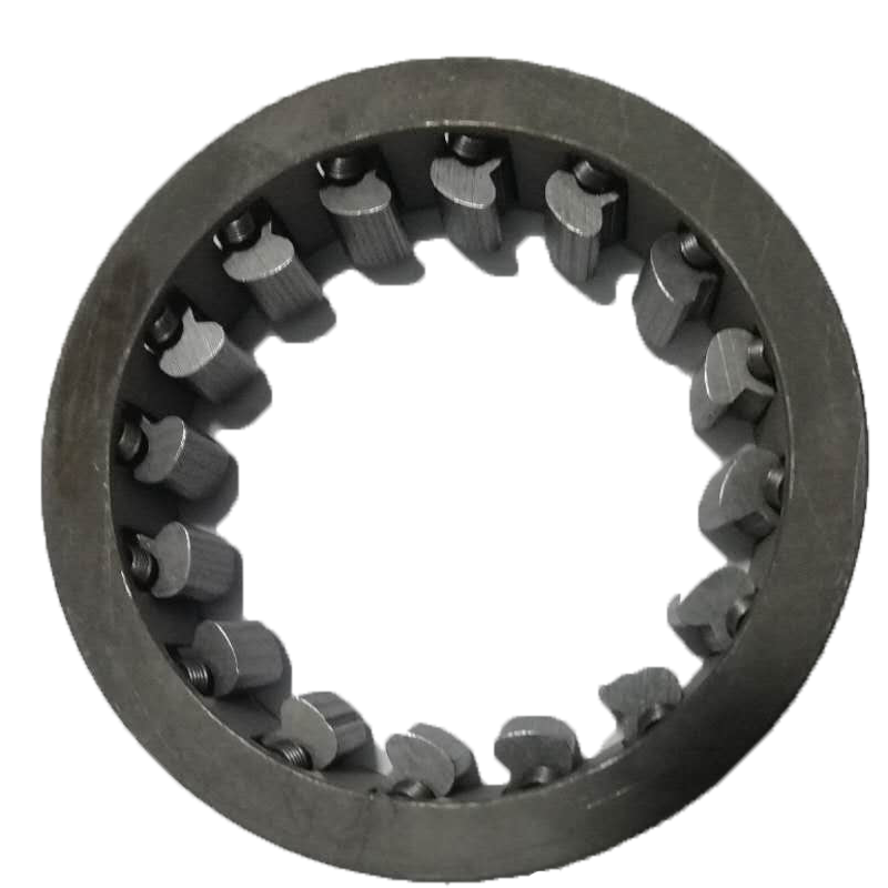
In high-capacity automatic transaxles and automotive drivetrains, the one-way sprag clutch is the ultimate mechanical gatekeeper. Many fleet MRO managers and aftermarket distributors mistakenly rely on standard-grade, single-cage freewheels that lack sufficient stability under extreme cyclic loading. When subjected to continuous thermal stress or sudden torque spikes, low-grade sprags experience a devastating phenomenon known as element rollover—where the cams flip past their locking angles, skating across the races and dumping destructive metal shaving contamination into the transmission oil circuit.
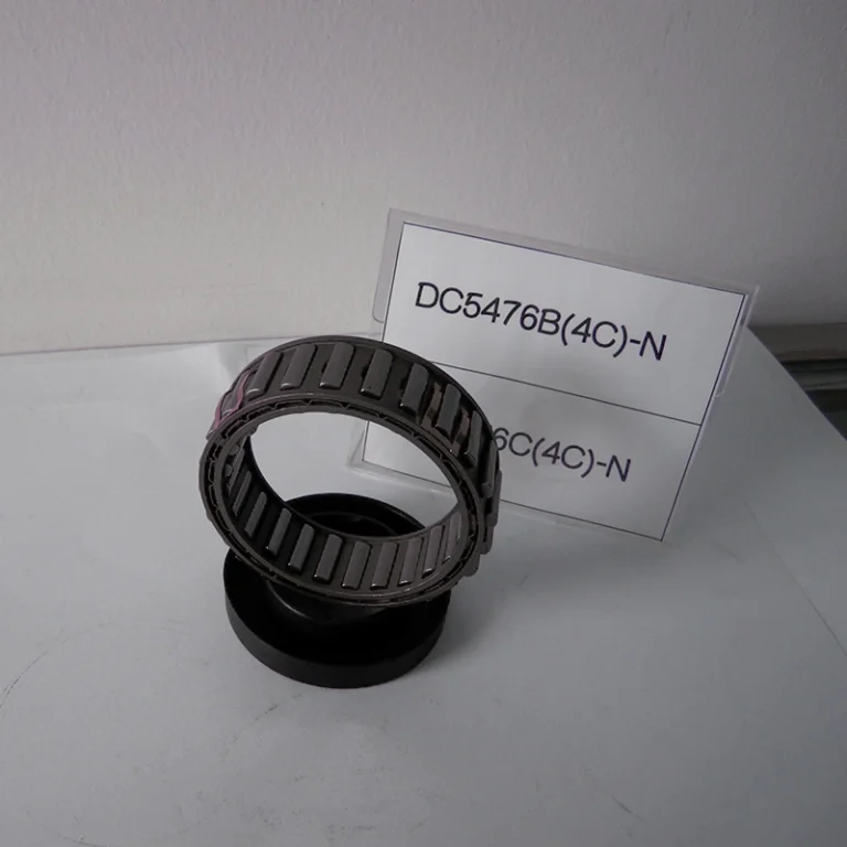
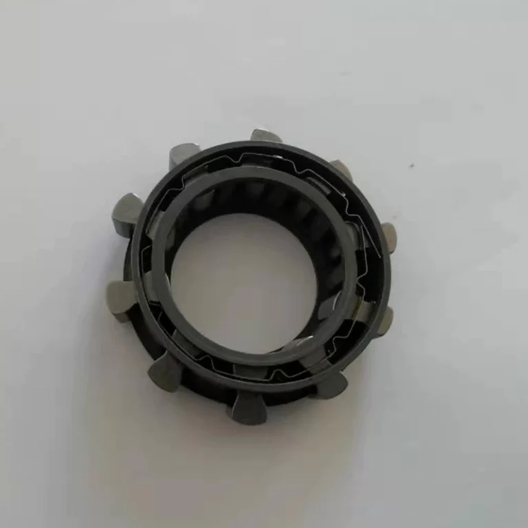
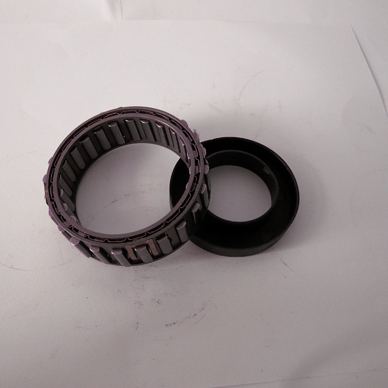
This technical guide explores how migrating to premium, drawing-compliant double-cage sprag matrices stabilizes powertrain torque transfer and eliminates mechanical slippage.
Quick Answer
To completely eliminate element rollover and secure instantaneous, zero-slip reverse locking under peak automotive loads, deploying an upgraded Double-Cage (DC) Sprag Matrix is essential. By mechanically synchronizing every independent cam element within a dual-steel cage framework, this design forces the torque load to distribute 100% evenly. This completely prevents asymmetric twisting, drastically minimizes freewheeling drag friction, and extends transmission rebuild lifecycles.
Comparative Specs: Single-Cage vs. Premium Double-Cage Components
| Engineering Performance Metric | Standard Single-Cage Component | Premium Double-Cage Assembly (LST DC/CL) |
| Torque Distribution Uniformity | Poor (Individual sprags can lag) | Perfect (Synchronized engagement) |
| Resistance to Element Rollover | Low (Prone to collapse under shock) | Extreme (Mechanical stop protection) |
| Freewheeling Friction Drag | Higher (Asymmetric contact pressure) | Minimized (Uniform lift-off dynamics) |
| Micro-Angular Backlash | 1.5° – 3.0° | Near-Zero (Instantaneous lockup) |
| B2B Service Lifecycle | Short (Frequent MRO replacements) | Extended Heavy-Duty Endurance |
Step-by-Step Inspection & Installation Protocol
Step 1: Execute Sub-Micron Race Auditing
Sprag clutches do not feature integrated bearings; they rely entirely on the mating shaft hub and housing drum races. Use a digital outside micrometer to verify sub-micron geometry tolerances. Any surface scoring or flat spots will cause premature failure.
Step 2: Confirm Lockup Vector Direction
Manually test the sprag assembly on the bench before final casing enclosure. It must freewheel seamlessly and silently in its designated overrunning direction and lock up solid instantly in the opposite direction.
Frequently Asked Questions
Q: What causes a transmission sprag clutch to “skate” instead of locking?
Skating occurs when the mating races are worn beyond sub-micron tolerances, or when the sprag energizing springs lose tension due to thermal breakdown, preventing the cams from biting into the race.
Q: Can I use standard industrial sprags in automotive torque converters?
No. Automotive torque converters experience intense fluid pressure fluctuations and rapid RPM shifts that require specialized dual-cage configurations (like the DC or CL Series) to prevent element rollover.