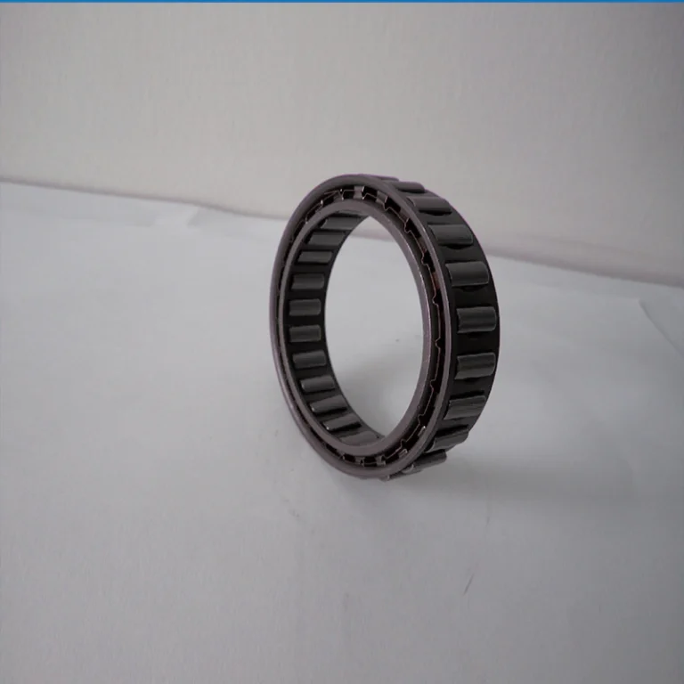

Mitigating Driveline Failure: The High-Stakes Reality of Sprag Clutch Selection
In high-capacity industrial powertrains, an unscheduled shutdown is rarely just an inconvenience—it is a catastrophic financial and safety liability. Consider a 1,200-foot inclined bulk handling conveyor transporting 2,500 metric tons of copper ore per hour. If an inferior mechanical backstop slips during an unexpected motor trip, the reversing mechanical kinetic energy can accelerate the entire conveyor system backward in fractions of a second. The resulting failure destroys gearboxes, shreds conveyor belting, and creates an immediate, life-threatening hazard for maintenance personnel. In high-speed dual-drive setups, such as combined electric motor and auxiliary steam turbine drives on municipal water feed pumps, an overrunning clutch failure can back-drive an idle prime mover past its structural yield limits, causing catastrophic rotor burst.
Securing reliable mechanical backstopping, indexing, and freewheeling performance requires uncompromising kinematic design, precision metallurgy, and verifiable manufacturing tolerances. This technical engineering guide breaks down the physics of sprag wedge engagement, provides sizing formulas based on AGMA and ISO protocols, presents comprehensive performance specifications, and outlines direct wholesale supply frameworks for high-volume OEMs and industrial operations managers seeking minimum Total Cost of Ownership (TCO).
Kinematics & Anatomy: The Mechanics of Sprag Overrunning Clutches
A one-way sprag clutch is a directional freewheel transmission mechanism that transmits rotational torque in one direction while instantaneously idling (freewheeling) in the opposite direction. Unlike roller-ramp clutches that rely on cylindrical rollers traversing inclined planar ramps, a sprag clutch utilizes precision-machined, cam-profiled strut components (sprags) positioned in the annular space between concentric cylindrical inner and outer raceways.
The Cam Profile and Strut Geometry
The cross-section of each individual sprag is not symmetrical; it exhibits two distinct cam curvatures characterized by a contact radius larger than the annular gap between the raceways. As relative rotation occurs in the driving direction, friction between the raceways and the sprag profile wedges the sprags outward, increasing their effective height through an action termed strut engagement.
The fundamental physical condition for engagement is governed by the friction coefficient (μ) between the sprag and the race surface, and the contact angle (α). Engagement without dynamic slip occurs when:
tan(α) ≤ μ
Where:
- α (Contact Angle): The angle formed between the normal line at the point of contact and the radial centerline of the sprag assembly (typically engineered between 3.5° and 8.5° depending on the torque-to-bore ratio).
- μ (Friction Coefficient): The static friction coefficient, which must remain adequate under hydrodynamic boundary layer lubrication conditions (μ ≈ 0.08 to 0.12 in oil-immersed applications).
If the contact angle α exceeds the arctangent of μ, instantaneous micro-slip occurs. This slippage generates localized friction temperatures exceeding 800°C within microseconds, accelerating Hertzian surface fatigue, race scouring, and rapid mechanical breakdown. Precision-engineered sprag clutches utilize progressive cam geometry, maintaining a controlled contact angle throughout the elastic deformation range of the raceways under extreme shock loads.
Cage Architecture & Energizing Systems
To ensure uniform load sharing among dozens of individual sprags, the internal assembly utilizes precision cages and energizing springs:
- Expanding Garter Springs: High-tensile stainless steel or beryllium copper circular coils threaded through the internal pockets of the sprag array. The spring maintains continuous, low-force contact between the sprags and both raceways, ensuring zero-backlash engagement upon directional reversal.
- Individually Energized Leaf Springs: Used in extreme vibration and severe shock environments. Each sprag operates with its own independent leaf spring clip, eliminating kinematic interference if one pocket experiences localized particulate contamination.
- Double-Cage Technology: In applications featuring rapid acceleration rates (e.g., > 1,200 RPM/sec), a double cage forces all sprags to tilt synchronously. This eliminates “sprag skewing,” a failure mode where misaligned sprags carry an uneven share of the torque load, triggering cascade destruction.
Centrifugal Lift-Off Mechanism (Sprag Lift-Off “Z” Geometry)
For high-speed overrunning applications, continuous hydrodynamic rubbing between the sprag profile and the inner or outer raceway causes parasitic drag, localized heat, and mechanical wear. To eliminate this issue, engineers use centrifugal lift-off sprags. By shifting the center of gravity of the sprag relative to its pivot axis, centrifugal force generated during high-speed rotation overcomes the spring energizing force at a calculated speed threshold.
When the rotation speed surpasses this engineered lift-off speed (Nlift), the sprags physically tilt away from the mating raceway, establishing a continuous hydrodynamic air/oil gap (typically 0.05 mm to 0.15 mm). In this condition, friction and component wear drop to zero, enabling millions of continuous freewheeling operating hours without mechanical degradation.
Comparative Analysis: Mechanical Overrunning Technologies
Selecting the optimal freewheeling mechanism requires evaluating kinematic limits, maximum torque density, angular backlash, and long-term maintenance cycles across operating types. The following comparison highlights structural trade-offs between modern sprag clutches and traditional alternative technologies.
| Parameter / Metric | LST Precision Sprag Clutch | Roller-Ramp Clutch | Wrap-Spring Clutch | Ratchet & Pawl Mechanism |
|---|---|---|---|---|
| Torque Density (Nm/kg) | High (180 – 320 Nm/kg) | Medium (90 – 160 Nm/kg) | Low-Medium (50 – 110 Nm/kg) | Low (30 – 70 Nm/kg) |
| Backlash / Engagement Lag | Zero (Continuous Contact) | Near-Zero (< 0.5°) | Moderate (1° – 3°) | High (5° – 45° tooth spacing) |
| Max Freewheel Speed (RPM) | Up to 15,000 (with Lift-off) | Up to 6,000 | Limited (< 1,500) | Very Low (< 400) |
| Shock Load Capacity | Superior (Dynamic Cam Load Sharing) | Moderate (Ramp Plastic Deformation Risk) | Poor (Tang Shearing) | High (Tooth Shear Mode) |
| Indexing Frequency Limits | Up to 1,200 cycles/min | Up to 400 cycles/min | Up to 250 cycles/min | Up to 120 cycles/min |
| Typical Maintenance Interval | 15,000 – 40,000 operating hours | 10,000 – 20,000 operating hours | 3,000 – 6,000 hours | 2,500 – 5,000 hours |
Calculations & Sizing: Engineering the Margin of Safety
Improper clutch sizing leads directly to premature raceway indentation (brinelling) or catastrophic dynamic slippage. Plant engineers must evaluate operational torque against ANSI/AGMA 6013 standards rather than relying solely on nameplate motor power ratings.
1. Nominal Operating Torque Calculation
Compute the baseline mechanical torque applied to the clutch using the delivered system shaft horsepower and continuous operating speed:
Tnom = (5,252 × P) / N
Where:
- Tnom: Nominal continuous torque (lb-ft). (Multiply by 1.3558 to yield Newton-meters [Nm]).
- P: Input shaft power (Horsepower, HP).
- N: Shaft speed at the clutch mounting location (RPM).
2. Applying System Service Factors (K-Factor)
Dynamic peak loads, prime mover characteristics, driven load inertia, and continuous duty cycles mandate that design engineers incorporate a dedicated Service Factor (SF):
Tdesign = Tnom × SF
Recommended minimum service factors under industrial operating guidelines:
- Electric Motor Drive with Non-reversing Uniform Load: SF = 1.50 – 1.75
- Internal Combustion Engine Drives (Piston Reciprocation): SF = 2.00 – 2.50
- Inclined Bucket Elevators & Heavy Slag Conveyors: SF = 2.50 – 3.50 (To counter structural shock and thermal stretch)
- High-Frequency Indexing Drives (Feeder Tables, Punch Presses): SF = 3.00 – 4.50
3. Centrifugal Lift-Off Verification
When selecting a sprag clutch equipped with lift-off elements for freewheeling inner or outer races, verify that minimum operating speeds exceed the lift-off threshold under all ambient temperature conditions:
Noperating_min ≥ 1.15 × Nlift
Operating below this 1.15 safety margin causes “hunting” or erratic contact between the sprags and raceways, leading to accelerated friction wear, lubricant breakdown, and premature failure.
Product Line Specifications: LST Industrial Wholesale Range
The LST engineered sprag clutch product line covers diverse industrial applications, from high-precision food packaging indexers to severe-duty mine backstops. The matrix below outlines operational parameters for our primary wholesale industrial configurations.
| LST Series | Design Configuration | Bore Range (mm) | Rated Torque (Nm) | Max Overrun Speed (RPM) | Standard Lubrication |
|---|---|---|---|---|---|
| LST-CKA | Self-Contained Bearing Supported, Integral Seals | 12 – 150 | 60 – 28,000 | 1,000 – 7,200 | Synthetic ISO VG 68 Oil / NLGI #2 Grease |
| LST-MG | High-Torque Backstop with Bolted Torque Arm Flange | 35 – 320 | 1,500 – 580,000 | 250 – 1,800 | Circulating Heavy Gear Oil (ISO VG 220/320) |
| LST-RSFW | Centrifugal Lift-Off Sprag (Outer Race Free) | 30 – 240 | 850 – 140,000 | Up to 14,500 (Freewheel) | Synthetic Jet Turbine Oil / Low Viscosity ISO 32 |
| LST-NF | Non-Bearing Supported Compact Profile (Thru-Shaft) | 8 – 100 | 25 – 9,500 | 1,200 – 8,500 | Oil Bath Immersion (System Integrated) |
Materials, Metallurgy, and Regulatory Frameworks
At wholesale manufacturing volumes, continuous structural reliability depends heavily on strict metallurgical quality control. The Hertzian contact stresses experienced at the tangential engagement interface often exceed 2,800 to 3,500 MPa. Material purity and specific heat treatment profiles are non-negotiable for long service life.
Steel Specifications and Heat Treatment
LST raceways are manufactured from high-purity, vacuum-degassed AISI 52100 (100Cr6) bearing steel or forged AISI 8620 case-carburizing alloy steel. Critical processing controls include:
- Surface Hardness: The inner and outer raceway tracks undergo carburizing or precision induction heat-treating to achieve a controlled surface hardness of 60 to 64 HRC (Rockwell C Scale). This prevents micro-indentation during sudden shock engagement.
- Case Hardness Depth: Effective case depth is maintained between 1.2 mm and 2.8 mm, providing a smooth hardness transition to a tough, resilient structural core (32 to 40 HRC) that absorbs severe mechanical shocks without brittle fracture.
- Sprag Metallurgical Profiling: Individual sprags are produced from through-hardened 52100 alloy steel or advanced sintered powder alloys treated with carbonitriding. This yields a micro-hardness approaching Vickers HV 800-900 for exceptional wear resistance under boundary friction conditions.
- Surface Roughness Tolerances: Raceway contact surfaces are superfinished to an average surface roughness of Ra ≤ 0.2 μm (8 μin), while out-of-round geometric tolerances are held within 0.005 mm (0.0002 in).
Industrial Compliance and Testing Standards
LST manufacturing facilities operate under comprehensive global quality protocols:
- ISO 9001:2015: Audited and certified quality management systems covering the full production cycle, from raw bar stock to final assembly.
- ANSI/AGMA 6013-B16: Design criteria and load calculations for industrial backstops and freewheel assemblies in enclosed gearboxes.
- OSHA 1926.555 & ASME B20.1: Safety standards for continuous conveyors and related industrial material-handling equipment requiring positive mechanical backstops.
- EN 10204 3.1 Certification: Certified chemical and physical material test reports (MTRs) provided for all major forged components in every wholesale shipment.
- ATEX Directive 2014/34/EU: Explosion-proof certifications (Zone 1/21) for backstop units destined for hazardous dust or vapor mining operations.
Total Cost of Ownership (TCO): Direct Wholesale vs. Component Failure
Procurement teams evaluate sprag clutches based on more than initial component purchase price. A low-cost unit manufactured with inconsistent raceway carburization, poor cage stabilization, or non-certified materials introduces substantial financial risk across its operational life. The financial model below contrasts standard-grade commercial units with LST engineered-grade assemblies across a 5-year operating window in an automated packaging and distribution facility (operating 4,000 hours annually).
| Cost Driver over 5-Year Life Cycle | Standard Generic Sourcing | LST Wholesale Engineered Supply |
|---|---|---|
| Initial Purchase Price (Capex, 100 Units) | $14,500 ($145/unit) | $22,000 ($220/unit, factory direct) |
| Replacement Parts Cost (5 Years) | $17,400 (120% replacement rate via wear) | $2,200 (10% standard maintenance cycles) |
| Unscheduled Driveline Downtime Cost | $140,000 (35 hours total @ $4,000/hr) | $0 (Zero unplanned failure events) |
| Routine Maintenance Labor Hours | $18,000 (300 hours @ $60/hr) | $4,500 (75 hours @ $60/hr) |
| Total 5-Year Cost of Ownership | $189,900 | $28,700 |
| Net Financial Advantage | Baseline | $161,200 Net Savings (84.8% TCO Reduction) |
Industrial Sourcing & Wholesale Evaluation Checklist
Before placing a volume purchase order for custom or standard one way sprag clutches, engineering and industrial procurement teams should verify that prospective manufacturing partners satisfy these essential technical and operational criteria:
Comprehensive Metallurgy Verification: Ensure every batch provides an EN 10204 3.1 chemical and hardness inspection certificate detailing case depth, core hardness, and micro-cleanliness ratings.
Dynamic Runout & CMM Inspection: Confirm raceway concentricity within 0.005 mm to prevent localized point-loading on individual sprags during freewheeling.
Verified Friction Coefficient Under Fluid Boundary: Require supplier laboratory test data validating the sprag engagement angle (α) against your specific operational lubricants.
Low-Temperature Lubrication Integrity: If machinery operates outdoors (e.g., ports, open-pit mines), verify that oil and grease formulations do not exceed NLGI dynamic viscosity limits at -40°C, which can cause sprags to stick in their pockets.
Precision Factory Direct Customization: Verify the manufacturer’s capacity to deliver custom keyway geometries, splined interfaces (DIN 5480, ANSI B92.1), and specialized high-torque bolt-circle designs on demand.
Ocean Transit Packaging Protection: Ensure volume wholesale shipments are sealed in heat-shrink Vapor Corrosion Inhibitor (VCI) hermetic packaging with desiccant systems to prevent salt-air oxidation during maritime transit.
Strategic Advantages of Wholesale Sourcing with LST
As a specialized manufacturer of heavy-duty transmission components, LST provides OEM design teams and high-volume industrial distributors with direct engineering support, transparent pricing, and rapid delivery programs tailored to demanding production schedules.
- Factory-Direct Pricing: By eliminating layered intermediary distribution channels, LST delivers premium, high-hardness sprag clutches at wholesale pricing directly from our automated manufacturing lines.
- Custom Modular Manufacturing: We specialize in custom bore configurations, bespoke outer race bolt circles, and specialized lift-off geometry engineered to your envelope dimensions with zero tooling surcharges on qualified volume runs.
- Continuous Supply Continuity: We operate dedicated vendor-managed inventory (VMI) frameworks and regional warehousing buffer stock within the United States, supporting uninterrupted Just-In-Time (JIT) production lines.
- 100% End-of-Line Testing: Every clutch assembly undergoes dynamic spin testing, engagement verification, and dimensional coordinate-measuring machine (CMM) validation prior to final export packaging.
Frequently Asked Questions (FAQ)
1. What is the fundamental operational difference between a sprag clutch and a roller ramp clutch?
While both mechanisms deliver overrunning functionality, their internal force distribution differs significantly. A roller-ramp clutch uses cylindrical rollers pushed up machined internal inclined planes. Under extreme shock loads, these rollers concentrate stress along narrow line contacts, which can indent the ramps and cause catastrophic dynamic slippage. A sprag clutch utilizes specialized, cam-profile struts operating between continuous, fully cylindrical concentric races. This design accommodates significantly more locking elements within the same envelope diameter, yielding 30% to 50% higher torque density, zero engagement backlash, and superior resistance to shock-load brinelling.
2. How does extreme cold or improper oil selection trigger clutch slippage?
Sprag clutches rely on dynamic physical contact driven by expanding garter springs or independent leaf springs. If a high-viscosity oil or an unapproved Extreme Pressure (EP) grease containing slippery chemical boundary additives (such as graphite, molybdenum disulfide, or excessive zinc dialkyldithiophosphate) is introduced, the static friction coefficient (μ) drops below the critical threshold: μ < tan(α). When this occurs, the sprags cannot gain traction on the inner race and slip continuously across the metal surface without locking, generating extreme friction heat that ruins the clutch assembly within seconds. Always adhere to LST-approved lubrication specifications.
3. Can an LST one-way sprag clutch be re-oriented in the field to reverse the drive direction?
Yes. The majority of LST non-bearing and modular bearing-supported series (such as our LST-CKA and LST-NF configurations) are fully symmetrical. Reversing the freewheeling direction from clockwise (CW) to counter-clockwise (CCW) is accomplished simply by removing the unit from the drive shaft, flipping it end-for-end 180 degrees, and reinstalling it along the keyway interface. Units with directional torque arms or asymmetric integrated fluid pump manifolds must be specified for the correct rotational direction (CW or CCW viewing the primary input hub face) when ordering at wholesale volumes.
4. What documentation accompanies bulk wholesale shipments from LST?
All wholesale OEM delivery containers are accompanied by comprehensive engineering and compliance documentation. This includes EN 10204 3.1 Material Test Reports (MTRs) detailing chemical composition and dynamic tensile properties, surface-hardness depth charts, dynamic CMM radial runout verification certificates, and an ISO 9001 compliance audit trail. Export shipments destined for the US and European markets feature serialized batch tracking, clear customs compliance codes, and protective anti-corrosive VCI packaging suited for long-term warehouse storage.
Secure Factory-Direct Wholesale Pricing for Your Production Lines
Do not allow critical driveline components to become single-point operational vulnerabilities. Partner with LST to secure high-torque, precision-machined sprag clutches backed by direct engineering support, documented metallurgical testing, and factory-direct wholesale pricing. Connect with our technical application team today to request a wholesale engineering catalog, review CAD models, or obtain an expedited production quote for your application.