An uncontrolled rollback on a loaded inclined conveyor is one of the most hazardous, capital-destructive catastrophic failures that can occur in bulk material handling. When a drive motor trips or a mechanical powertrain components shear under full operational load, gravity instantly reverses the flow of hundreds of tons of material. The resulting dynamic reverse acceleration routinely explodes gearboxes, shreds rubber belting, shears head-pulley shafts, and puts plant personnel in severe danger. Mitigating this catastrophic risk requires more than a conventional brake; it demands an uncompromising mechanical backstop clutch designed for instantaneous, zero-backlash torque arrest.
As an industrial-grade conveyor backstop clutch manufacturer, LST Sprag Clutch engineers and manufactures heavy-duty overrunning clutches, holdbacks, and anti-reverse components built to protect critical drivetrains. Sourced by gearbox manufacturers, industrial machinery OEMs, bulk handling integrators, and plant engineers across the United States, our one-way clutches deliver instantaneous engagement, exceptional torque resistance, and operational longevity under harsh industrial conditions. Whether your operation requires standard drop-in units or precision custom non-standard dimensions, this guide delivers the engineering criteria, sizing methodologies, and lifecycle assessments required to specify the optimal anti-runback device for high-stakes conveyor systems.
1. What Is a Conveyor Backstop Clutch? (Mechanical Anti-Reverse Protection)
A conveyor backstop clutch—also designated in industrial drive engineering as a holdback, backstopping clutch, or anti-reverse clutch—is a high-precision, one-way mechanical freewheel component installed along the conveyor drivetrain. Its function is twofold: during standard operation, it overruns freely in the forward conveying direction with minimal drag and minimal friction; the millisecond the input drive stops or rotational direction attempts to reverse, the internal locking elements lock mechanically between the inner and outer races, providing instant, rigid anti-reverse locking.
Unlike dynamic industrial disc or drum friction brakes that rely on electrical energization, hydraulic line pressure, or pneumatic actuation to engage, a mechanical backstop is completely autonomous. It requires no external sensors, control logic, or human intervention. Engagement occurs purely via mechanical geometry and gravity or spring pre-loading, ensuring fail-safe holdback operation even during complete plant blackouts.
Core Industrial Applications
Backstopping mechanisms are essential across continuous bulk handling infrastructure, including:
- Inclined Belt Conveyors: Preventing reverse belt travel when moving crushed stone, coal, ore, grain, cement, or biomass up steep inclines.
- Bucket Elevators: Neutralizing the continuous static head weight of vertically elevated material in feed, fertilizer, and cement silos.
- Gear Reducers & Drive Systems: Direct integration on the intermediate or low-speed shafts of parallel shaft, planetary, and right-angle gearboxes.
- Pumps, Fans, and Industrial Mixers: Preventing impeller back-spin caused by reverse fluid head or pipeline reflux.
2. Engineering Kinematics: Sprag vs. Roller-Ramp Mechanisms
Mechanical anti-runback devices generally leverage one of two primary mechanical locking technologies: sprag freewheel elements or ramp-and-roller assemblies. Understanding the operational differences between these mechanisms is vital for matching unit capabilities to machine demands.
Sprag Clutch Technology
A sprag backstop utilizes precision-ground, cam-profiled locking elements positioned between concentric cylindrical inner and outer races. During forward rotation, the contour of the sprags allows the lubricating film to sustain low-friction sliding or hydrodynamic lift-off. When the driving force ceases and reverse rotation begins, the sprags tilt and wedge securely between the races. Because a sprag unit incorporates a higher density of contact points along the annular space than a roller assembly, it offers an exceptionally high torque-to-weight ratio and compact radial dimensions.
Roller-Ramp Technology
Roller-ramp clutches utilize cylindrical rollers seated along precision-machined internal ramps on either the inner or outer race. Each roller is individually spring-loaded. Forward rotation drives the rollers down the ramps into the wider clearance zone, allowing the shaft to freewheel. Reverse motion forces the rollers up the converging ramps, wedging them tightly to halt movement immediately. For specific applications requiring robust impact resistance and predictable torque transmission, such as the AV / GV series ratchet roller type one-way clutch, roller mechanisms deliver consistent performance across dirty, shock-intensive environments.
Comparative Analysis: Holdback Mechanism Technologies
| Engineering Attribute | Sprag Backstop Clutch | Roller-Ramp Holdback | External Friction Brake (Caliper/Disc) |
|---|---|---|---|
| Backlash / Engagement Lag | Virtually Zero (Instantaneous camming) | Near-Zero (Minimal ramp wedge travel) | Variable (Air gap, reaction time) |
| Torque Density (Torque / Envelope) | Extremely High | Moderate to High | Low (Requires large envelope) |
| Overrunning Heat Generation | Low (With centrifugal lift-off: Zero) | Low to Moderate | N/A (Disengaged open air) |
| Power Failure Sensitivity | 100% Fail-Safe (Pure mechanical) | 100% Fail-Safe (Pure mechanical) | Requires spring-applied power release |
| Installation Location | High-speed, intermediate, or head shaft | Intermediate or low-speed drive shafts | High-speed shaft / Motor coupling |
3. Product Range: Standard Series & Industrial Configurations
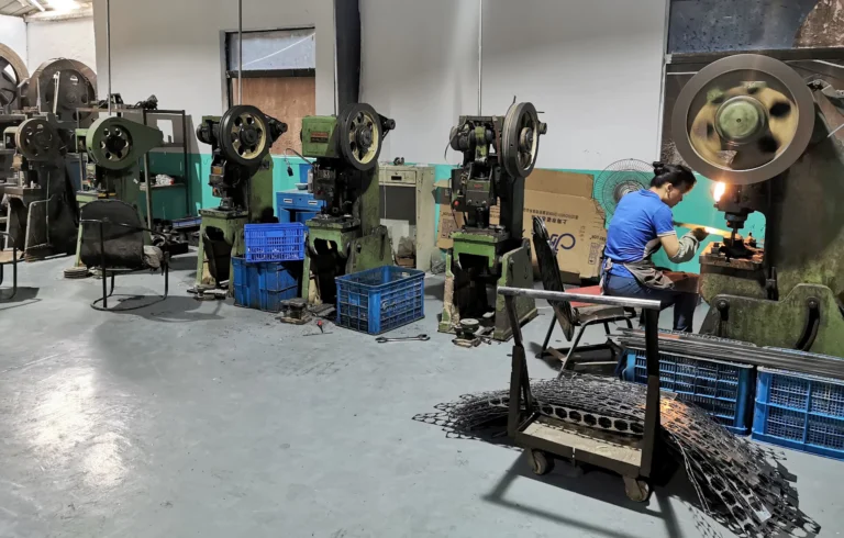
As a specialized conveyor backstop clutch manufacturer, LST Sprag Clutch produces a comprehensive portfolio of industrial one-way clutches machined entirely from high-grade bearing steel. Premium bearing steel delivers maximum surface hardness (HRC 60–64 after heat treatment), deep case hardening to prevent race brinelling, high dimensional stability, and prolonged fatigue resistance.
Comprehensive Industrial Series Overview
Our production facilities support global conveyor, bucket elevator, and power transmission assemblies through the following standard and configurable series:
- BS Series (Conveyor Holdbacks): Specifically engineered for direct mounting onto the low-speed head pulley shafts of inclined belt conveyors and bucket elevator drives. Equipped with an integrated torque arm designed to transfer locked reaction torque directly to the structural framework.
- MG & MZ Series: General-purpose cam clutches designed for overrunning and backstopping duties on reducer output shafts, intermediate shafts, and packaging systems. The MZ series features integrated ball bearings for self-contained concentric alignment.
- FSO Series: High-speed overrunning sprag clutches optimized for external lubrication systems, offering maximum rotational speeds on gearbox intermediate shafts.
- AV & GV Series: Roller-ramp freewheels featuring individual spring-loaded rollers and robust torque retention, widely selected for heavy machinery backstopping.
- ASNU & TFS Series: Non-bearing supported roller-type freewheels requiring adjacent customer-supplied radial bearings to maintain race concentricity; suited for compact space envelopes.
- DC, BWC & RSBW Series: Modular sprag cages and freewheels engineered for seamless incorporation directly between machine-ground housing and shaft surfaces.
- CSK, HF & HFL Series: Precision drawn-cup and miniature bearing-clutch assemblies utilized across automated sorting lines, auxiliary feeding conveyors, and lightweight industrial drives.
Technical Selection: Series Comparison Matrix
| Series Designation | Internal Mechanism | Mounting Style | Optimal Conveyor Placement | Lubrication Compatibility |
|---|---|---|---|---|
| BS Series | Sprag / Cam with Torque Arm | Shaft mounted with keyway & torque arm | Head pulley shaft (Low Speed) | Grease or Sealed Oil Reservoir |
| MG / MZ Series | Precision Sprag | Flange / Keyed shaft mount | Reducer output or intermediate shaft | Oil bath or Synthetic Grease |
| FSO Series | High-Speed Sprag | Shaft keyed, bolted housing flange | Reducer high/intermediate shaft | Circulating Oil or Splash Oil |
| AV Series | Ramp and Roller | Centering bore, outer race keyed | Conveyor drives, auxiliary backstops | Grease or Oil Mist |
| ASNU Series | Roller Type | Press-fit / Keyed outer race | Internal gearbox integrations | Shared gearbox industrial gear oil |
4. Engineering Calculations: Sizing and Specifying a Conveyor Backstop
Sizing an anti-runback device requires evaluating both standard holding requirements and extreme dynamic shock loading. Sizing a backstop solely to the nominal motor horsepower is a frequent point of failure in bulk material engineering. Instead, the design must calculate the maximum reverse torque developed by the fully loaded inclined conveyor under breakdown or power-loss conditions.
Step 1: Calculating Static Breakdown Torque (The Pure Gravity Component)
The static rollback torque ($T_{st}$) present at the head pulley shaft when a loaded inclined conveyor arrests is calculated using the vertical lift, material capacity, and mechanical efficiency:
Tst = [ (Q × H) / (3.6 × v) ] × (D / 2) × ηr
Where:
- Tst: Static rollback torque at head shaft (N·m)
- Q: Design material conveying capacity (metric tons per hour)
- H: Total net vertical lift of the inclined conveyor (m)
- v: Operational belt speed (m/s)
- D: Diameter of the head drive pulley including lagging (m)
- ηr: Reverse mechanical efficiency of the conveyor system (typically taken between 0.85 and 0.90 to account for reverse idler friction losses)
Step 2: Torque Sizing via Connected Drive Power (Standard Engineering Check)
When engineering backstops installed directly onto intermediate reducer shafts or motor extensions, calculate the nominal drive torque ($T_n$) based on operational motor power:
Tn = (9550 × P) / n
Where:
- Tn: Nominal driving torque (N·m)
- P: Nameplate motor rating (kW)
- n: Rotational speed of the mounting shaft (RPM)
Step 3: Applying CEMA & Industrial Service Factors
Per the Conveyor Equipment Manufacturers Association (CEMA) guidelines, backstops must not operate at unity design limits. Dynamic belt stretch, belt recoil, dynamic kinetic rebound upon sudden trip, and uneven load distribution across multi-drive pulleys introduce substantial instantaneous shock loads. Therefore, the required minimum design backstop torque rating ($T_{req}$) is:
Treq = Tst × SF
Recommended Service Factors (SF) for backstopping clutch selection:
- Standard inclined conveyors (single head drive, uniform feed): SF = 1.5 to 1.75
- Heavily loaded inclined conveyors / Bucket elevators (lumpy material, high drop impact): SF = 2.0 to 2.5
- Multi-drive setups with load-sharing backstops: SF = 2.5 to 3.0
5. Mounting Locations: Low-Speed vs. High-Speed Shaft Deployment
Determining the position of the backstopping clutch within the mechanical drivetrain affects safety margins, mechanical stress, footprint, and overall capital expenditure.
Option A: Direct Head-Pulley Shaft Mounting (Low-Speed Shaft – Recommended)
Mounting a BS Series holdback device directly on the extended low-speed shaft of the head drive pulley is widely recognized as the safest configuration. In this arrangement, torque is held directly at the terminal component driving the conveyor belt. If the reducer intermediate shafts break, coupling elastomeric inserts shear, or primary chains fail, the head pulley remains rigidly locked by the holdback. The trade-off: rotational speeds are low (often 20–80 RPM), requiring a backstop engineered for massive torque holding capacity.
Option B: Gearbox Intermediate or High-Speed Shaft Mounting
Mounting an FSO, MG, or ASNU series unit onto the gearbox high-speed input shaft or an intermediate gear cluster allows the use of a substantially smaller physical clutch. Because shaft speeds are higher, the holding torque required to resist the load is reduced inversely proportional to the gear ratio ($T_{high-speed} = T_{pulley} / i$). However, if a gear tooth shears, an internal shaft fractures, or an internal coupling disconnects downstream within the gearbox, the holdback cannot arrest the head pulley, leaving the conveyor unprotected against catastrophic rollback.
6. Industrial Compliance and Regulatory Frameworks
Deploying certified backstop clutches is not merely a matter of equipment longevity—it is an enforced occupational safety mandate throughout modern bulk handling facilities. Operating uncertified, undersized, or worn anti-runback devices exposes facilities to severe regulatory penalties and civil liability:
- MSHA (Mine Safety and Health Administration) Title 30 CFR: Explicitly mandates reliable, fail-safe anti-rollback protection on all inclined slope conveyors operating across underground and surface mining operations. Under MSHA safety rules, a failure of anti-reverse systems resulting in belt runaway constitutes a major safety violation.
- OSHA 29 CFR 1926.555 & 1910.218 (Conveyor Safety): Enforces that any inclined, decline, or vertical conveyor operating under load must be fitted with mechanical anti-rollback devices or backstops to prevent material from sliding backward onto operators during emergency stops.
- CEMA Safety Standards (Standard 550 & 400 Series): Provides technical standard operating guidelines regarding mechanical engineering allowances, backstop ratings, and inspection protocols for continuous bulk belt handling.
- ISO 9001:2015 Manufacturing Standards: LST Sprag Clutch maintains documented quality management protocols across dimensional tolerances, material certifications, hardness validation, and torque verification for all bearing steel components.
7. Total Cost of Ownership (TCO) & Procurement Checklist
When procuring holdback devices, forward-looking procurement directors weigh Capex against long-term risk and Opex. An undersized, low-quality backstop may save hundreds of dollars at purchase, yet an unplanned failure causes catastrophic damage exceeding hundreds of thousands of dollars in ruined belting, destroyed gearboxes, months of downtime, and regulatory fines.
Lifecycle Cost Modeling: OEM Direct vs. Low-Grade Alternatives
| Cost Metric | LST Sprag Clutch (Engineered Bearing Steel) | Commercial-Grade Off-Brand Units |
|---|---|---|
| Initial Capital Cost (Capex) | Moderate (Factory-direct competitive pricing) | Low initial purchase cost |
| Standard Lead Time | 1 Week (Standard products in stock) | 6 to 16 weeks (often imported without local stock) |
| Customization Capabilities | Custom non-standard bore, keyway, & dimensions | Fixed catalogue items only; no modular alterations |
| Wear Resistance & Service Life | Long service life; vacuum-degassed bearing steel | High risk of brinelling and premature sprag slipping |
| Downtime Risk Exposure | Negligible; calculated safety factor resilience | High probability of unexpected slippage or sudden release |
Industrial Procurement Checklist for Backstops
- Confirm Full Dynamic Torque Requirements: Verify that your calculations factor in maximum slope, peak material density, belt weight, and a CEMA service factor of ≥ 1.5 to 2.5.
- Verify Shaft Diameters & Keyway Specifications: Provide exact millimetric or imperial shaft tolerances. At LST Sprag Clutch, standard products are held in inventory, while non-standard bores and custom keyway profiles are machined to OEM prints.
- Evaluate Overrunning Speed Thresholds: Compare continuous forward drive shaft RPM against the maximum allowable overrunning RPM limit of the selected clutch series to prevent inner/outer race overheating.
- Torque Arm Clearances: Ensure the mounting site includes adequate structural clearance for the torque arm, allowing sufficient tangential freedom while arresting rotational force against an anchor stop without binding.
- Define Lubrication Regime: Match oil or grease formulations to operating ambient temperatures (-40°C arctic grease vs. high-heat mineral oils for kiln and smelter conveyors).
8. Installation, Alignment, and Maintenance Protocols
To realize the long service life engineered into bearing steel one-way clutches, maintenance personnel must follow strict mechanical assembly and lubrication guidelines.
Torque Arm Installation Best Practices
On shaft-mounted units such as the BS Series, the torque arm resists the reverse rotational torque. A critical installation rule: never rigidly bolt down the torque arm end. Rigidly bolting the torque arm creates an over-constrained mechanical system. When the head shaft inevitably deflects or wobbles under dynamic conveyor loading, an over-constrained torque arm transfers massive radial side loads directly into the backstop internal support bearings, causing rapid bearing destruction. Instead, fit the torque arm end between parallel angle stops or inside a slotted clevis bracket with a specified clearance (typically 10 mm to 15 mm) to allow axial and radial movement while securing rotational torque.
Lubrication Management
- Extreme Pressure (EP) Additive Warning: Unless explicitly engineered for specialized EP formulations, sprag clutches must never use gear oils containing friction-modifier or extreme pressure (EP) slip additives (such as graphite, molybdenum disulfide, or heavy chlorine-phosphorus packages). These additives reduce the internal friction coefficient below the critical engagement threshold, causing sprags to slide rather than lock during reverse motion.
- Periodic Oil Checks: On oil-filled backstops, verify sight-glass levels monthly. Perform the initial oil change after 500 hours of run-in operation, followed by regular oil replacements every 3,000 to 5,000 operational hours or annually.
Frequently Asked Questions (FAQ)
What is the typical production and delivery lead time for backstop clutches?
For standard industrial backstop clutches across our AV, ASNU, MG, MZ, FSO, BS, TFS, DC, BWC, RSBW, CSK, HF, and HFL series, products are maintained in stock. Our standard manufacturing and dispatch lead time is one week. For custom non-standard bores, special keyways, or tailored flange dimensions, lead times are scheduled directly with our engineering department.
Can you manufacture custom non-standard backstop clutch dimensions for OEM retrofits?
Yes. In addition to our broad standard catalog, LST Sprag Clutch provides custom non-standard sizes. Our manufacturing facility handles custom inner race shaft bores, special spline interfaces, unique keyway dimensions, and customized torque arm geometry tailored to replace obsolete legacy holdbacks or fit proprietary OEM machinery.
Are samples available for engineering qualification and testing?
Yes, prototype and evaluation samples can be provided for qualified machinery OEMs, conveyor system integrators, and distributors. Samples are supplied on a freight collect basis. Reach out to our technical sales team with your operational parameters to initiate a sample request.
What material is utilized in the internal components of LST Sprag Clutches?
All functional load-bearing components—including the sprags, rollers, inner races, and outer races—are manufactured from high-grade bearing steel. This material provides exceptional surface hardness, wear resistance under continuous overrunning, high torque transmission stability, low noise, and maximum operational life.
Partner with a Dedicated Conveyor Backstop Clutch Manufacturer
Whether you are designing a high-capacity overland mining conveyor, retrofitting aging bucket elevators in a cement terminal, or building next-generation industrial gear reducers, protecting your equipment against uncontrolled rollback is an absolute priority. LST Sprag Clutch delivers proven mechanical reliability, short lead times, direct factory pricing, and rigorous quality standards.
Contact our technical engineering team today to review your torque calculations, verify dimensional envelope drawings, or order your initial evaluation unit.