

A single sprag rollover failure under a 2,500 Nm transient hydraulic shock load does not merely slip—it destroys the planetary gearset, contaminates the transmission fluid loop with powdered martensitic steel, and triggers thousands of dollars in warranty or field downtime. In heavy commercial planetary transmissions, off-highway powershift gearboxes, and multi-speed passenger vehicle automatics, the freewheel overrunning clutch is the linchpin of smooth gear handoffs and reaction torque holding. As transmission architectures scale from 6-speed configurations to 8-, 9-, and 10-speed platforms, selecting an experienced, engineering-led sprag type one way clutch for automatic transmission supplier is the difference between achieving 500,000 miles of maintenance-free operation and sustaining catastrophic field campaigns.
At LST Sprag Clutch, we design, engineer, and manufacture precision-profiled sprag elements, resilient energizing spring cages, and custom-ground inner and outer raceways. Leveraging advanced finite element analysis (FEA), multi-body elastodynamic modeling, and specialized metallurgies, LST produces one-way clutches engineered to withstand high torsional accelerations, aggressive transmission fluid chemistries, and extreme thermal cycling across automotive, commercial, and heavy industrial drivelines.

1. Kinematics and Working Principles of Sprag Clutches in Automatic Transmissions
A sprag-type one-way clutch is a freewheeling mechanical diode that transmits high torque in one rotational direction while free-spinning with minimal parasitic drag in the opposite direction. Unlike roller-ramp designs that rely on inclined planes machined into an inner or outer hub, a sprag clutch operates between two concentric, cylindrical raceways. This geometric configuration delivers the highest torque-to-envelope ratio of any mechanical freewheeling mechanism.
1.1 The Cam Geometry and Strut Action
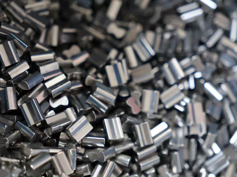
The core of the sprag assembly is an array of precision-formed, non-cylindrical cam elements (“sprags”). Each sprag possesses an asymmetrical profile characterized by two distinct cam contact radii ($R_1$ and $R_2$) eccentric to the pivot axis. When relative rotation occurs in the driving direction, the sprag tilts, and its dimension along the strut axis widens, wedging tightly between the concentric inner and outer races through a dynamic wedge angle (strut angle, $alpha$).
To prevent destructive slip, the mechanical engagement must satisfy the fundamental friction-locking criterion:
Mechanical Engagement Condition:
tan(α) ≤ μ
Where:
• α = Contact strut angle (typically between 3.5° and 8.5° depending on the cam profile).
• μ = Instantaneous coefficient of friction between the carburized race surface and the sprag cam under boundary lubrication conditions (typically 0.08 – 0.12 in automatic transmission fluid, ATF).
If $tan(alpha)$ exceeds $mu$, the sprag loses traction, slips across the race, and experiences instantaneous “sprag rollover”—plastic deformation of the cam profile that destroys the mechanism’s ability to lock under subsequent load cycles.
1.2 Dynamic Lift-Off Mechanics in High-Speed Freewheeling
During cruising gears or continuous engine overrunning states, parasitic drag across disengaged friction packs and mechanical diodes penalizes fuel economy and generates unwanted heat. To mitigate dynamic parasitic losses, LST Sprag Clutch utilizes precision-engineered centrifugal lift-off sprag geometry.
By shifting the center of gravity of the individual sprag relative to its pivot axis, centrifugal force acting on the rotating elements counters the energizing spring force at a predetermined threshold speed (the lift-off speed). Once exceeded, a microscopic hydrodynamic clearance (typically 15 to 35 μm) opens between the sprag cam profile and the inner race, achieving absolute zero-wear, zero-drag freewheeling. This lift-off profile is indispensable for high-input-speed applications such as hybrid e-axles and multi-speed automatic overdrive carriers.
2. Engineering Architecture: Metallurgies, Cages, and Raceway Optimization
LST Sprag Clutch supplies fully integrated clutch packages—including standalone sprag cages, inner/outer race assemblies, and integrated reaction hubs—engineered to interface seamlessly with planetary carriers, torque converter stators, and direct-drive transmission shafts. Table 1: Material Science and Heat Treatment Specifications of LST Sprag Assemblies
| Component | Material Grade | Heat Treatment Process | Surface Hardness | Effective Case Depth | Surface Finish (Ra) |
|---|---|---|---|---|---|
| Sprag Elements | SAE 52100 / GCr15 High Carbon Bearing Steel | Through-Hardened, Cryogenic Stabilized | 60 – 64 HRC | Through-hardened | ≤ 0.20 μm |
| Inner Race | SAE 8620 / 20CrMo Carburizing Alloy | Controlled Atmosphere Gas Carburizing (CQI-9) | 58 – 62 HRC (Core: 32–40 HRC) | 1.0 – 1.5 mm | ≤ 0.35 μm |
| Outer Race | SAE 4320 / DIN 17CrNiMo6 Alloy Steel | Deep-Case Carburizing + Martempering | 60 – 63 HRC (Core: 35–45 HRC) | 1.2 – 1.8 mm | ≤ 0.35 μm |
| Retention Cages | Polyamide 46 (30% GF) / Stamped Brass | Precision Injection / Fine Blanking | N/A | N/A | Smooth, deburred |
| Energizing Springs | AISI 302 Stainless / 17-7 PH Precipitation Hardened | Stress Relief Tempering | 45 – 50 HRC | Elastic limit verified | Bright finished |
2.1 Cage Architecture: Single-Cage vs. Double-Cage Configurations
A frequent failure mode in high-vibration off-highway automatic transmissions is sprag skewing—the axial twisting of individual sprags relative to the raceway centerlines under severe torsional acceleration. To counteract skewing, LST provides two distinct retaining designs:
- Single-Cage System with Ribbon Spring: Utilized in cost-sensitive, high-volume automotive light-duty applications. The continuous ribbon spring exerts a steady preload torque on every sprag pocket, maintaining synchronized movement under steady operating dynamics.
- Precision Double-Cage System with Independent Spring Tabs: Engineered for severe shock-load duty, such as off-highway construction and commercial truck automatics. Two concentric cages mechanically capture both the upper and lower trunnions of every sprag, enforcing parallel kinematic alignment across the entire circumference. Even under 40G driveline shock loads, sprags are physically restrained from skewing, ensuring balanced load distribution across the entire contact track.
3. Mathematical Modeling & Selection Calculations
Accurate sizing of a sprag type one way clutch prevents premature raceway spalling and ensures uncompromised mechanical reliability. When evaluating an application profile, LST applications engineers utilize structural and tribological models to verify capacity.
3.1 Static and Dynamic Torque Capacity Formulation
The gross nominal torque rating ($T_N$) of a fully complemented sprag pack is defined by the equilibrium of normal forces and structural geometry:
TN = Z · Fn · ri · tan(α)
Where:
• Z = Total quantity of sprags engaged along the raceway circumference.
• Fn = Normal contact force exerted between the sprag cam and raceway (N).
• ri = Radius of the inner raceway (m).
• α = Dynamic gripping/strut angle at the instantaneous engagement point (radians).
3.2 Hertzian Contact Stress Analysis
Because the sprag-to-race interface is a line contact between two non-conforming convex/concave cylindrical surfaces, maximum contact stress must be controlled below the fatigue endurance limit of the carburized layer:
σH = √ [ (Fn / L) · ( (1/Rsprag) + (1/Rrace) ) / ( π · ( ((1 – ν12)/E1) + ((1 – ν22)/E2) ) ) ]
Where:
• L = Effective axial contact length of the sprag (mm).
• Rsprag, Rrace = Instantaneous cam radius of curvature and raceway radius (mm). Note: for an inner race, the sign is positive; for an outer race, it is negative (internal contact).
• E1, E2, ν1, ν2 = Young’s Modulus (210 GPa) and Poisson’s ratio (0.3) of the mating alloy steels.
• Design Threshold: LST limits static peak Hertzian contact stress σH ≤ 3,800 MPa under maximum emergency stall torque, and continuous dynamic cyclic stress σH ≤ 2,200 MPa to guarantee an $L_{10h}$ service life exceeding 12,000 operational hours.
3.3 Freewheeling Parasitic Drag Loss
Overrunning drag torque ($T_{drag}$) governs the parasitic efficiency penalty of the transmission:
Tdrag = Z · Fspring · μhydro · ri
Where: Fspring is the radial preload of the energizing spring and μhydro is the hydrodynamic viscous shear coefficient governed by ATF viscosity grade (e.g., Dexron VI, Mercon LV, or Allison TES-295) and operating temperature (-40°C to +150°C).
4. Technical Comparison: Sprag Clutches vs. Competing Overrunning Technologies
Selecting the optimal freewheel configuration requires balancing torque density, overrunning speed ceiling, radial packaging profile, and manufacturing cost. The table below details how LST sprag designs compare against roller-ramp and controllable multi-plate friction packages. Table 2: Comparative Architecture Matrix for Transmission Freewheel Mechanisms

| Performance Metric | LST Sprag Type One-Way Clutch | Roller-Ramp Clutch | Multi-Plate Friction Clutch |
|---|---|---|---|
| Torque Density (Nm/cm³) | Extreme (180 – 260) | Moderate (90 – 140) | Low (35 – 60) |
| Radial Cross-Section Height | Ultra-Compact (8 – 16 mm) | Large (20 – 38 mm) | Large (40 – 90 mm) |
| Overrunning Max Speed Limit | Up to 12,000 RPM (with lift-off) | Limited (≤ 5,500 RPM) | High (≤ 9,000 RPM) |
| Backlash / Engagement Play | Zero instantaneous lash (< 0.5°) | Slight (1.5° – 3.0°) | Hydraulic latency (50 – 150 ms) |
| Parasitic Drag Losses | Near-zero above lift-off speed | Continuous spring-drag friction | High viscous drag between wet plates |
| Assembly Complexity & Actuation | Passive mechanical / Self-contained | Passive mechanical | Requires electro-hydraulic valve block |
5. Cross-Platform Transmission Compatibility & OEM Field Applications
LST Sprag Clutch manufactures interchangeable drop-in replacement units and co-engineered custom assemblies built to strict OEM specifications across the global automotive, commercial trucking, and heavy equipment markets. Table 3: Common OEM Transmission Applications and LST Engineering Specifications
| OEM / Transmission Family | Clutch Position / Functional Role | Torque Rating (Nm) | Overrunning Speed (RPM) | LST Product Configuration |
|---|---|---|---|---|
| Allison Transmission® 3000 / 4000 Series (e.g., Forward No. 2) | Forward Reaction / Planetary Low Hold | 3,200 – 5,800 | 3,600 | Heavy-duty dual cage, precision ground inner/outer raceways |
| ZF® Friedrichshafen 6HP, 8HP (8HP55, 8HP70, 8HP90), 9HP | Torque Converter Stator Freewheel / 1st Gear Brake Hold | 650 – 1,400 | 7,500 | Centrifugal lift-off outer cam profile, polyamide-cage cartridge |
| Caterpillar® / Komatsu® Off-Highway Powershift Transmissions | Directional Clutch Pack / Planetary Countershaft Hold | 4,500 – 12,000 | 2,800 | Forged outer ring, deep carburized case (1.8mm), steel cage tabs |
| Ford® / GM® (GMC, Chevrolet, Cadillac, Buick) 6L80/90, 10R80, 10L90 Transmissions | Intermediate 1-2 Holding Sprag / Low-Reverse Sprag | 1,100 – 2,100 | 6,800 | Precision stamped bronze cage, ribbon energized, micro-honed races |
| Mercedes-Benz® / Volkswagen (VW) Group / Bentley 7G-Tronic, 9G-Tronic, DSG Dual-Clutch Units | Stator Reaction Freewheel & Reversing Shaft Hold | 800 – 1,600 | 8,200 | High-speed dynamic lift-off elements with high-temp fluoroelastomer seal sets |
| Volvo® / John Deere® / Massey Ferguson® Agricultural IVT & Heavy Powershift | Hydro-Mechanical Infinitely Variable Range Unit Hold | 2,800 – 6,500 | 3,200 | Double-cage reinforced strut assembly, customized spline-bore inner race |
Our engineering division also manufactures specialized, high-integrity sprag configurations for premium performance drivelines, including Jaguar and Mazda longitudinal gearboxes, where package weight, NVH dampening, and rapid lockup response are paramount. For further technical specifications on our complete product range, review our [Industrial Freewheel Selection Guide](https://www.lstclutch.com/freewheel-selection-guide).
6. Quality Assurance, Metrology & Compliance Frameworks
In high-reliability automatic transmissions, one-way clutch quality cannot be inspected in at the packaging line—it must be engineered into the molecular grain structure of the raceway and the dimensional micron tolerances of the sprag cam profile. LST manufacturing operations comply strictly with automotive quality frameworks:
- IATF 16949:2016 Certified: Fully audited quality management system across high-volume production lines, including advanced product quality planning (APQP), production part approval process (PPAP Level 3 standard), and full lot traceability down to raw wire rod and forgings.
- AIAG CQI-9 (Special Process: Heat Treat Assessment): All internal atmospheric gas carburizing furnaces, induction scanning rigs, and temper lines are certified under CQI-9 requirements with continuous pyrometric datalogging, ensuring exact case depths, zero retained austenite spikes, and decarburization-free working surfaces.
- Profile Metrology via Formscan CNC: Each sprag cam geometry is scanned on CNC coordinate measuring machines (CMM) and Taylor Hobson contour profilometers. Contact profile deviations are constrained to within ±0.002 mm of mathematical CAD curves to ensure uniform load sharing among all sprag elements.
- Ultrasonic Non-Destructive Testing (NDT): 100% volumetric inspection of raw outer ring forged blanks to detect non-metallic inclusions, subsurface seams, or micro-voids prior to machining, complying with ASTM E1444 magnetic particle and ASTM A609 ultrasonic test standards.
- Dynamic Spin-Loss and Endurance Testing: In-house dyno testing benches subject sample lots to accelerated life testing: 1,000,000 shift-lock cycles at 130°C ATF sump temperatures and rapid deceleration cycles to replicate severe engine braking shock loads. Review our [Clutch Quality and Dyno Testing Facilities](https://www.lstclutch.com/quality-testing-facilities) for dynamic validation parameters.
7. Total Cost of Ownership (TCO) & Reliability Analysis
Procuring a sprag type one-way clutch based solely on initial piece-part acquisition cost (CapEx) can be an expensive operational error for Tier-1 transmission assemblers and industrial fleet remanufacturers. The actual operational expense (OpEx) is dictated by the clutch’s mean time between failures (MTBF), its contribution to overall transmission parasitic efficiency, and the mitigation of catastrophic drivetrain warranty incidents.
7.1 Common Modes of Failure and LST Countermeasures
- Sprag Rollover / Inversion: Occurs when excessive stall torque drives the cam angle past its critical wedging limit.
LST Countermeasure: Engineered geometric positive-stop cams that physically lock against adjacent sprags before reaching the rollover angle, preventing inversion even under severe hydraulic pressure spikes. - Raceway Brinelling and Spalling: Caused by cyclical Hertzian stresses exceeding the elastic limit of the raceway steel.
LST Countermeasure: Vacuum-degassed 8620 and 4320 alloys deep-carburized to 60–64 HRC with controlled residual compressive surface stress fields exceeding -800 MPa. - Spring Fatigue & Dynamic Loss of Energization: High-frequency cyclic oscillation causes spring tab fracture, leading to unaligned sprag engagement and destructive slip.
LST Countermeasure: Precipitation-hardened 17-7 PH and continuous wave stainless spring ribbons designed for an infinite fatigue life threshold (> $10^7$ dynamic flexing cycles).
7.2 TCO Financial Impact
In high-mileage commercial vehicle operations (e.g., class 8 linehaul or municipal transit buses equipped with Allison or ZF units), a premature one-way clutch failure results in an estimated $6,500 to $12,000 in direct overhaul costs, towing, and chassis downtime. Utilizing LST extended-durability dual-cage sprag assemblies increases the transmission overhaul threshold from 300,000 miles to beyond 750,000 miles, delivering an estimated 400% ROI on the component procurement differential over the lifecycle of the vehicle fleet.
8. Strategic B2B Procurement and Sourcing Evaluation Checklist
Before issuing a Request for Quotation (RFQ) to a sprag type one way clutch for automatic transmission supplier, technical procurement teams and transmission chief engineers should use the following audit checklist:
Technical Sourcing & Quality Audit Checklist
- Raceway Integration: Are the inner and outer raceways supplied as a matched, pre-honed cartridge set, or must they be machined directly into your customer shaft and clutch housing? If integrated directly, confirm that your shaft metallurgy and heat-treat depth can achieve ≥ 58 HRC with Ra ≤ 0.35 μm.
- Boundary Lubrication Compatibility: Has the sprag geometry been analyzed for the specific additive package of your factory-fill transmission oil (e.g., friction modifiers, anti-wear zinc dialkyldithiophosphates, and shear-stable viscosity index improvers)?
- Centrifugal Lift-Off Verification: Is the outer race or the inner race the overrunning member? (Sprags must be custom-profiled differently for inner-race overrunning vs. outer-race overrunning lift-off).
- Dynamic Shock Factor Application: Has a minimum 2.0x to 2.5x service factor been applied over the maximum engine-brake or stall torque to absorb torsional chatter from torque converter lockup transients?
- Sub-tier Metallurgy Audits: Does the supplier provide full melt-source traceability to reputable steel mills with low oxygen/inclusion ratings (e.g., DIN EN 10247 or ASTM E45 Method A)?
- Packaging and Corrosion Inhibitors: For overseas export shipping, are the clutch assemblies vacuum-sealed in VCI (Vapor Corrosion Inhibitor) packaging pre-lubricated with a compatible assembly oil?
To initiate a comprehensive application review or request 2D/3D CAD models for physical mockups, submit your system torque profiles and shaft constraints directly to our [Custom Driveline Engineering Team](https://www.lstclutch.com/custom-engineering).
9. Frequently Asked Questions (Technical & Procurement)
Q1: Can an LST sprag clutch assembly replace an OEM roller-ramp clutch in an existing automatic transmission housing?
Answer: In most cases, yes. Sprag clutches possess substantially higher torque density than roller-ramp units of identical physical volume. Replacing a roller-ramp clutch with an LST sprag cartridge typically requires installing an outer adapter ring or a custom outer raceway due to the smaller radial envelope of the sprag set. This upgrade significantly increases torque safety margins, reduces parasitic freewheeling drag, and eliminates ramp wear issues common to high-mileage transmissions.
Q2: How does transmission fluid (ATF) chemistry affect sprag clutch engagement and life?
Answer: Sprag engagement relies on controlled friction (boundary lubrication regime). Transmission fluids with excessively high concentrations of friction-reducing (slippery) boundary layer additives can lower the coefficient of friction below the dynamic strut angle threshold (tan α > μ), causing sprag slip during cold starts or rapid torque spikes. Conversely, uninhibited aggressive oils can lead to micro-welding and premature freewheel wear. LST analyzes customer ATF chemical specifications to tune the sprag cam radius and spring energization force to the exact lubrication characteristics of your transmission.
Q3: What are the minimum requirements if our plant prefers to finish-machine our own inner and outer raceways?
Answer: If your plant integrates the raceways directly onto your transmission input/counter shafts or carrier drums, the running tracks must be carburized or induction hardened to 58–62 HRC with an effective case depth of at least 1.2 mm. The raceways must be precision finish-ground or hard-turned to a surface roughness of Ra ≤ 0.35 μm, with roundness and cylindricity maintained within 0.008 mm. LST supplies the free sprag-cage cartridge pack along with detailed manufacturing prints and tolerance stack-up documentation for your shaft machining lines.
Q4: What is the typical lead time for custom-engineered prototype sprag assemblies vs. volume OEM production runs?
Answer: For custom-engineered transmission prototypes requiring specialized cam tooling and bespoke cage designs, LST typically delivers validated First Article PPAP samples within 6 to 8 weeks. For volume production matching existing transmission geometries (e.g., Allison Forward No. 2, ZF 8HP series, Caterpillar/Komatsu off-highway platforms), standard production batch orders are fulfilled within 3 to 4 weeks with containerized or express air logistics options for North American Tier-1 manufacturing hubs.