
In high-torque powertrain systems, the margin between operational continuity and catastrophic mechanical failure is measured in fractions of a millimeter. When an off-the-shelf overrunning mechanism experiences sprag rollover under transient shock loads, or succumbs to premature micro-pitting from elastohydrodynamic lubrication (EHL) breakdown, the downstream consequences are severe: sudden loss of drive, uncontrolled conveyor rollback, turbine runaways, or catastrophic transmission lockups. For operations directors, plant managers, and mechanical drive engineers, selecting a dedicated custom sprag clutch manufacturer is not simply an exercise in component sourcing—it is a critical risk-mitigation strategy for the entire driveline.
Industrial machinery often operates well beyond the baseline assumptions of generic supplier catalogs. Cyclic shock loading, extreme thermal gradients, shaft deflection, and non-concentric runouts demand custom-engineered contact geometries, advanced metallurgy, and application-specific cage biasing. As a specialized OEM sprag clutch partner, LST provides end-to-end design, precision grinding, metallurgical validation, and high-volume manufacturing of custom freewheel solutions engineered specifically to survive where standard components fail.
1. The Mechanical Science of Sprag Clutches: Kinematics & Wedge Geometry
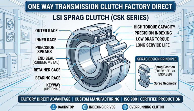
A sprag clutch functions as a precision one-way freewheel mechanism designed to transmit high rotational torque in one direction while instantaneously overrunning (freewheeling) in the opposite direction. Unlike roller-ramp clutches that rely on cylindrical rollers wedging into tapered planar ramps, a sprag freewheel utilizes asymmetrical, double-cam-profiled struts positioned within the annular space between concentric cylindrical inner and outer raceways.
The Fundamental Strut Engagement Condition
The engagement mechanics of a custom one way clutch depend entirely on the geometric profile of the sprag. The cross-section features two distinct radii: a smaller radius that permits free rotation when overrunning, and an eccentric, elongated cam dimension that wedges between the races during driving engagement. For instantaneous, non-slip torque transmission, the dynamic contact angle (α) between the sprag cam profile and the raceway must satisfy the fundamental self-locking friction condition:
tan(α) < μ
Where μ represents the static coefficient of friction between the carburized raceway surface and the sprag contact face under dynamic boundary lubrication conditions. In typical lubricated industrial applications, μ ranges between 0.06 and 0.12. If mechanical deflection, thermal expansion, or geometric machining error causes the contact angle to exceed this threshold, the sprag experiences catastrophic slip, generating extreme localized frictional heat, galling, and immediate mechanical rollover.
Centrifugal Lift-Off vs. Continuous Engagement Geometry
Custom engineering dictates whether an application requires contact-type sprags or centrifugal lift-off designs:
- Contact Sprags with Energizing Springs: Ideal for low-to-medium overrun speeds and precision indexing applications. Continuous spring biasing ensures instantaneous engagement with zero backlash, making it essential for feed tables, stepping drives, and safety backstops.
- Centrifugal Lift-Off Sprags (Lift-Off at Inner or Outer Race): Designed for ultra-high-speed overrunning drives, such as multi-motor industrial blowers, auxiliary turbine drives, and starter-generator systems. By optimizing the center of gravity (CG) of the sprag relative to its pivot axis, centrifugal forces counteract spring tension at a predetermined rotational speed (the lift-off speed, typically 600 to 1,500 RPM). Once disengaged, a hydrodynamic air or fluid gap eliminates mechanical contact entirely, dropping frictional drag and parasitic heat dissipation to zero and ensuring near-infinite service life.
2. Why Off-the-Shelf Sprag Clutches Fail in Severe Service
Catalog-standard freewheels are built to nominal dimensional standards and median torque profiles. When deployed in severe heavy equipment or high-stress automotive environments, systemic failure modes frequently emerge:
Dynamic Shock Loads and Raceway Brinelling
Catalog ratings typically publish maximum static torque alongside a nominal dynamic factor. However, applications such as mining conveyors, vibratory compactors, and hybrid powertrain decouplers experience transient torque spikes up to 300% to 500% of nominal drive torque. Standard race wall thicknesses cannot absorb the resultant radial hoop stress, resulting in plastic deformation (brinelling) of the inner race and subsequent sprag seizure.
Angular Misalignment and Torsional Vibration
Commercial freewheels assume near-zero angular misalignment (under 0.03 mm / 0.001 in). In real-world multi-bearing gearboxes, structural deflection under load introduces angular misalignment. This concentrates the contact stress on the outer edges of the sprags, precipitating edge-loading fatigue, cage fracture, and premature spalling.
Lubricant Degradation and Roller Rollover
Off-the-shelf units often mandate specific, highly refined turbine oils. In mobile heavy machinery or industrial processing, contamination by moisture, particulate ingress, or the mandatory use of standard extreme-pressure (EP) gear oils containing friction-reducing zinc or sulfur additives can reduce the friction coefficient below tan(α), leading to dynamic slippage and destructive catastrophic rollover.
3. Comprehensive Technical Comparison: Freewheel Architectures
Selecting the optimal overrunning mechanism requires analyzing the operating trade-offs between different mechanical one-way clutch topologies.
| Performance Parameter | Sprag Freewheel (Custom Engineered) | Roller-Ramp Clutch | Ratchet & Pawl Mechanism |
|---|---|---|---|
| Torque Density (Nm/kg) | Extremely High (Up to 3,500 Nm/kg) | Moderate (1,000 – 1,800 Nm/kg) | Low to Moderate (500 – 900 Nm/kg) |
| Backlash / Engagement Angle | Near Zero (< 0.1°) | Low to Moderate (1° – 3°) | High (Dependent on tooth pitch, 5° – 15°) |
| Maximum Overrunning Speed | Up to 15,000+ RPM (Lift-off design) | Moderate (Up to 3,500 RPM) | Very Low (< 500 RPM due to pawl wear) |
| Indexing Precision Frequency | Up to 1,200 cycles/min | Up to 300 cycles/min | Unsuitable for high-speed indexing |
| Radial Space Requirement | Minimal (Compact annular envelope) | Substantial (Requires internal cam ramps) | Large (Requires external ring gears) |
| Shock Load Absorption | High (Multi-sprag load sharing) | Moderate (Limited by roller contact count) | Low (Prone to single-tooth shear) |
Standard Catalog Units vs. LST Custom OEM Engineering
For custom industrial and automotive applications, adapting standard products forces compromises in shaft sizing, casing weight, and overall reliability. The following engineering matrix highlights how tailored solutions compare against baseline catalogue components:
| Engineering Feature | Standard Catalog Freewheel | LST Custom Sprag Clutch Solutions |
|---|---|---|
| Raceway Integration | Separate inner/outer rings requiring keys and sleeves | Direct shaft/housing raceway induction hardening |
| Spring Energizing System | Standard garter spring (uniform load profile) | Custom individual leaf/clip springs or segmented dual garter |
| Cage Kinematics | Stamped thin steel or basic polyamide | Precision CNC machined bronze, PEEK, or reinforced steel cages |
| Lubrication Tolerance | Restricted to non-EP thin mineral oils | Optimized sprag profile compatible with synthetic gear oils & ATF |
| Operating Temperature | -20°C to +80°C (-4°F to 176°F) | -40°C to +180°C (-40°F to 356°F) with specialized metallurgy |
4. Custom Engineering Solutions: LST Product Architecture
As a specialized sprag clutch supplier, LST designs and manufactures complete, application-matched assemblies as well as modular drop-in sprag elements.
DC Series Sprag Freewheel Clutches
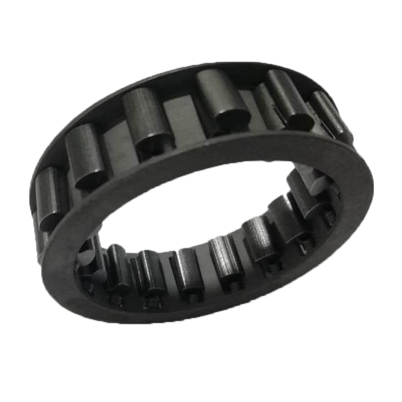
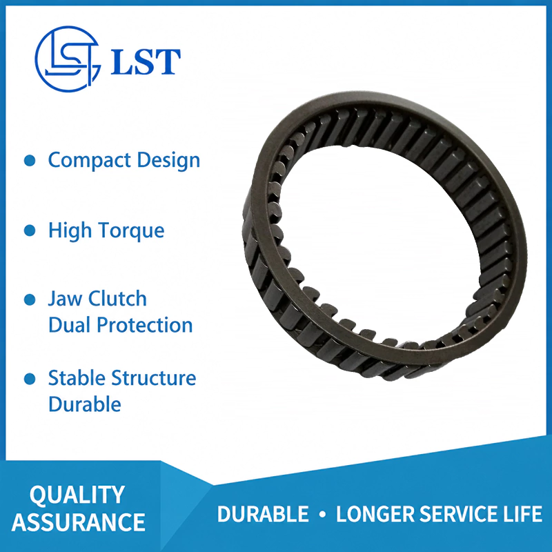
Our core modular engineering offerings include the DC series sprag freewheel clutch product line. These assemblies utilize a self-contained double-cage system with individual spring-energized sprags. Key design features include:
- Zero Inner-Ring Overhead: The double-cage assembly can be mounted directly between customer-supplied inner shafts and outer housing bores, eliminating the weight, radial runout, and expense of secondary sleeves.
- Uniform Sprag Spacing: Precision-milled cage pockets prevent sprag skewing during instantaneous velocity differentials, ensuring 100% synchronized engagement across every individual strut.
- Drop-In Retrofit Flexibility: Engineered to interchange with existing global industrial footprints while delivering up to 20% higher dynamic torque ratings through optimized cam radiuses.
Automotive and Powertrain Overrunning Clutches
Modern hybrid drives, auxiliary starters, and automatic multi-speed transmissions demand low mass and high operational responsiveness. Through our specialized automotive sprag clutch engineering line, LST integrates complex internal splines, integral bearing supports, and precision hydrodynamic liftoff geometries directly into planetary gear assemblies. Our designs reduce spin-loss drag by up to 35% during extended high-speed freewheeling phases.
5. Engineering Mathematics: Calculations, Sizing, and Stress Modeling
Correct mechanical sizing requires thorough validation of static torque capacity, dynamic overrunning speeds, and raceway contact stress limits.
Torque Sizing and Service Factor Calculation
The operational drive torque (T_nom) is determined by motor horsepower and shaft rotational velocity:
T_nom (lb-ft) = (5252 × HP) / RPM | T_nom (Nm) = (9550 × kW) / RPM
To ensure long-term durability without slip or raceway fatigue, the minimum required clutch torque capacity (T_design) must incorporate an engineering service factor (S_f):
T_design = T_nom × S_f
Service factors must be selected based on the prime mover and driven load dynamics:
- Uniform Load (Electric Motor to Centrifugal Pump): S_f = 1.3 to 1.5
- Moderate Shock (Internal Combustion Engine to Gearbox): S_f = 2.0 to 2.5
- Severe Reversing/Vibratory Shock (Reciprocating Compressor, Crusher, Mining Conveyor): S_f = 3.0 to 4.5+
Hertzian Contact Stress Modeling
During torque lock-up, the sprag transmits load via contact surfaces on the inner and outer raceways. Maximum contact stress (σ_H) must be verified to prevent surface fatigue spalling:
σ_H = √ [ (F_n / L) × ( (1/R_sprag + 1/R_race) / (π × ( (1 – ν_1²)/E_1 + (1 – ν_2²)/E_2 )) ) ]
Where:
- F_n = Dynamic normal wedging force acting on each sprag
- L = Effective axial contact length of the sprag (mm)
- R_sprag, R_race = Radii of curvature of the sprag cam profile and raceway
- E, ν = Modulus of elasticity (typically 210 GPa) and Poisson’s ratio (0.3) of the bearing steels
For high-cycle industrial applications, LST limits peak working Hertzian contact stress to ≤ 2,800 to 3,200 MPa, preserving infinite-life elastohydrodynamic film separation when combined with prescribed lubrication regimes.
6. Advanced Metallurgy, Heat Treatment, and Surface Topography
The lifespan of a custom overrunning clutch is fundamentally determined by the metallurgy of the contact components. Substandard bearing alloys yield micro-crack propagation under cyclic Hertzian shear stress, leading to premature flaking.
Core Material Specifications
- Vacuum-Degassed SAE 52100 (100Cr6) High-Carbon Chromium Steel: Standard for precision-ground sprags and medium-duty inner/outer rings. Through-hardened to 60 – 64 HRC with deep cryogenic treatment (-120°C) to eliminate retained austenite, ensuring dimensional stability up to 150°C.
- Carburized AISI 8620 / 20CrNiMo Alloys: Utilized for high-impact industrial housings and integrated shafts. Carburized to an effective case depth of 0.8 – 1.4 mm, yielding a wear-resistant surface hardness of 60 – 63 HRC backed by a ductile, fracture-resistant core hardness of 32 – 40 HRC capable of withstanding dynamic shock reversals.
Surface Topography and Superfinishing
Surface roughness (Ra) plays a primary role in friction stability and sprag wear:
- Raceway Finish: Ground and isotropic superfinished to Ra ≤ 0.2 μm (8 μin). Eliminating micro-asperities ensures stable hydrodynamic wedge formation and prevents micro-galling during the overrunning cycle.
- Sprag Contact Profile: CNC profiled to continuous sub-micron tolerances, maintaining cam profile angular consistency within ±0.002 mm across entire production batches.
7. Quality Assurance, Testing Protocols, and International Compliance
Reliability requires strict testing and comprehensive traceability across the manufacturing process. LST operates under an ISO 9001:2015 quality management infrastructure. Every custom one way clutch design is validated using exhaustive physical test protocols:
- Dynamic Static-Slip Overload Testing: Testing clutches to mechanical destruction on high-capacity hydraulic torsion benches to verify ultimate yield torque, hoop stress resistance, and calculated safety factors.
- High-Speed Overrunning Endurance Cycles: Testing overrunning speeds up to 12,000 RPM over 1,000+ continuous hours to map thermal profiles, drag torque, centrifugal lift-off characteristics, and wear progression.
- High-Frequency Indexing Simulation: Validating contact sprag leaf-spring fatigue limits up to 10,000,000 continuous engagement cycles under full rated load.
- Spectrographic Material & NDT Validation: Full optical emission spectrometry (OES) verification on raw bar stock, accompanied by 100% magnetic particle inspection (MPI) on finished sprags and raceways to detect subsurface fissures.
LST designs and manufactures assemblies compliant with relevant industrial standards, including ANSI/AGMA 6013 (specifications for industrial gear drives), DIN 748 (shaft extensions), as well as OSHA 1910.262 conveyor backstop safety mandates and EU Machinery Directive 2006/42/EC.
8. Total Cost of Ownership (TCO) & Lifecycle Procurement Economics
Procurement teams are often pressured to source off-the-shelf standard freewheels based strictly on initial unit purchase price (Capex). However, this accounting model ignores the significant operational expense (Opex) caused by premature component failure, unpredicted driveline repairs, and unplanned plant downtime.
| Financial Lifecycle Metric | Low-Cost Off-The-Shelf Clutch | LST Custom Engineered Sprag Clutch |
|---|---|---|
| Initial Purchase Price (Unit Capex) | Baseline ($) | +20% to 40% initial investment ($$) |
| Expected Operating Lifespan | 8,000 to 12,000 hours (1 – 1.5 years) | 40,000 to 80,000+ hours (5 – 10+ years) |
| Parasitic Drag Energy Loss | Continuous drag during overrun (High kW draw) | Near zero drag with lift-off design (>90% drag reduction) |
| Scheduled Maintenance Interval | Every 2,000 hours (Oil flushes, re-shimming) | 10,000 to 20,000 hours (Self-contained, synthetic lube) |
| Risk of Unplanned Downtime | High (Rollover from shock, misalignment) | Extremely Low (Validated for actual driveline shock limits) |
| 5-Year Cumulative TCO | 300% – 800% of purchase price (Frequent failures) | Optimized (Lowest overall lifecycle expenditure) |
In high-throughput sectors like aggregate processing, port material handling, and steel manufacturing, an unplanned driveline outage costs between $15,000 and $100,000+ per hour. Investing in a custom-engineered solution that handles your system’s specific dynamic spikes is one of the most cost-effective investments an engineering team can make.
9. Application Engineering Case Profiles
High-Inclination Bulk Mining Conveyor Safety Backstops
Operational Challenge: An underground coal conveyor in West Virginia experienced periodic drive trips under full 2,500-ton/hour load. The standard catalogue backstop experienced severe torsional shock during sudden motor cutouts, leading to sprag rollover and dangerous backward belt acceleration.
LST Custom Solution: LST engineered a heavy-duty, torque-arm-mounted sprag backstop featuring an integrated fluid damper and an increased sprag complement using carburized 20CrNiMo raceways. The custom sprag profile accommodated transient peak torque loads of 185,000 Nm (a 2.8x increase over previous components) within the identical envelope dimensions, completely eliminating backstop slippage and ensuring full OSHA compliance.
High-Speed Turbine-Driven Starter Overrunning Clutch
Operational Challenge: A gas turbine auxiliary starting package experienced continuous freewheeling wear at 7,200 RPM, requiring clutch element replacements every 9 months due to spring burnout and race scuffing.
LST Custom Solution: LST deployed a custom centrifugal lift-off sprag freewheel. By precisely positioning the sprag mass center, lift-off was engineered to occur cleanly at 1,150 RPM. During continuous 7,200 RPM operation, the sprags lifted completely free of the inner raceway, dropping operating temperatures by 42°C and extending mean time between overhauls (MTBO) from 9 months to over 7 years.
10. Step-by-Step OEM Procurement & Specification Checklist
When collaborating with a custom sprag clutch manufacturer, providing detailed driveline operating data ensures an accurate, dependable design. Use this checklist during the design review phase:
- 1. Torque Profile:
- Nominal operational torque (Nm or lb-in).
- Maximum transient peak / shock torque.
- Direction of torque transmission (viewed from driving shaft end).
- 2. Velocity Parameters:
- Driving engagement speed (RPM).
- Overrunning speed of inner race (RPM) and outer race (RPM).
- Total percentage of operating cycle spent freewheeling vs. driving.
- 3. Dimensional & Mechanical Interfaces:
- Shaft diameter, tolerance, and surface hardness (if shaft acts as raceway).
- Housing bore diameter, material, and modulus.
- Allowable axial envelope length and overall radial diameter limits.
- Keyway, splined interface (DIN 5480, ANSI B92.1), or press-fit requirement.
- 4. Operating Environment:
- Ambient and localized operating temperature range (-40°C to +180°C).
- Lubrication method: Oil bath, continuous oil mist, grease, or dry lift-off.
- Lubricant chemistry (viscosity grade, presence of EP additives).
- Submersion, washdown, or exposure to abrasive particulate matter.
11. Frequently Asked Questions (FAQ)
Can I use standard Extreme Pressure (EP) gear lubricants with custom sprag clutches?
Conventional sprag clutches are vulnerable to standard EP gear lubricants containing aggressive friction-modifying additives like molybdenum disulfide (MoS2) or zinc dialkyldithiophosphate (ZDDP). These additives generate a low-friction chemical film that can reduce μ below the sprag contact angle threshold, precipitating slippage. However, LST can engineer custom one way clutch profiles with adjusted cam angles and textured micro-geometries, or specify compatible high-load industrial oils, ensuring dependable lock-up even under severe shock conditions.
What is the primary difference between a sprag clutch and a roller-ramp clutch?
A sprag clutch utilizes double-radius asymmetrical cam struts mounted between concentric, smooth cylindrical races, allowing for a large number of contact elements within a compact annular space. This yields substantially higher torque density and faster engagement than roller-ramp designs, which require individual ramps and wedging rollers that consume significant radial envelope space. Roller-ramp clutches are often limited to lower overrunning speeds, whereas sprag designs can achieve tens of thousands of RPM with centrifugal lift-off geometries.
How does LST calculate the fatigue life (L10h) of a custom freewheel assembly?
Dynamic life calculations combine modified Hertzian contact stress analysis with dynamic overrunning wear tracking. For engagement cycles, we calculate fatigue life via the ISO 281 dynamic load rating framework, accounting for material purity, effective case depth, raceway superfinishing factors, and operating oil viscosity. For lift-off overrunning freewheels, bearing lifespan and seal durability serve as the limiting design metrics, typically yielding designed service lives well in excess of 50,000 operating hours.
Can LST manufacture sprag clutches to fit existing obsolete machinery footprints?
Yes. A key advantage of working with a dedicated sprag clutch supplier like LST is our reverse engineering and drop-in retrofit capability. We routinely recreate, re-engineer, and upgrade legacy, obsolete, or high-cost European and American overrunning clutches (including custom shaft sizes, splines, or torque-arm configurations) with upgraded metallurgy and enhanced torque ratings, without requiring any redesign of your surrounding gearbox architecture.SAE J1087 — One-Way Clutches: Nomenclature and Terminology
Partner with LST for Engineered Freewheel Reliability
Standard components inevitably lead to compromised driveline performance. Eliminate downtime risks, reduce high-speed overrunning drag, and guarantee absolute engagement reliability with custom-engineered one-way freewheel solutions built specifically for your machinery.
Ready to review your mechanical drawings or collaborate on a high-torque prototype? Explore our comprehensive portfolio at LST Products Catalog or reach out directly to our application engineering team at autospragclutch.com to begin your custom design evaluation today.