
In heavy-duty power-shift transmissions and commercial vehicle torque converters, the stator freewheel clutch operates under some of the most punishing tribological conditions in modern mechanical engineering. A single sprag rollover event or micro-slip under full stall torque does not merely degrade efficiency—it triggers catastrophic hydrodynamic cavitation, oil circuit contamination via metallic swarf, and irreversible transmission lockup. In heavy mining haulers, agricultural tractors, and Class 8 commercial vehicles, such an operational failure translates into unscheduled downtime costs exceeding $12,000 to $30,000 per shift.
Selecting a high-integrity OEM torque converter sprag assembly supplier is a critical engineering decision that dictates drivetrain MTBF (Mean Time Between Failures), torque multiplication efficiency, and warranty liability. As a dedicated manufacturer, LST Sprag Clutch specializes in custom-engineered sprag type one-way clutches, utilizing precision-stamped cam profiles, customized metallurgical heat treatments, and tailored inner and outer races. This technical pillar guide details the kinematics, metallurgy, failure mitigation, and total cost of ownership (TCO) benchmarks procurement directors and chief powertrain engineers require when sourcing critical freewheel components.
1. Kinematics and Mechanics of Stator Sprag Clutches
The torque converter stator sprag assembly functions as an automated hydrodynamic mechanical switch. During the torque multiplication phase (stall through low-speed ratio, typically $0 < i < 0.85$), the fluid redirected by the turbine strikes the back of the stator blades, generating a counter-rotational torque. The sprag assembly must instantaneously lock against the stationary stator shaft, grounding the reaction torque to the transmission casing to achieve torque multiplication ratios up to 2.5:1.
Once the drivetrain reaches the coupling point ($i approx 0.85$ to $0.90$), fluid dynamics change angle, striking the front of the stator vanes. At this transition, the sprag clutch must instantly release, freewheeling with near-zero drag torque to prevent the stator from becoming an aerodynamic restriction that chokes high-speed efficiency.
Sprag Geometry and Strut Locking Angle Mechanics
Unlike cylindrical roller clutches that contact planar ramp angles, a sprag utilizes an asymmetrical, dual-radius cam geometry. The mechanics of engagement are governed by the strut angle (α), defined as the angle between the contact normal vector and the radial line connecting the sprag pivot to the race center. For self-locking to occur without slip, the strut angle must strictly satisfy the friction condition:
α ≤ arctan(μ)
Where μ is the coefficient of static friction between the sprag cam surface and the raceway under automatic transmission fluid (ATF) boundary lubrication (typically ranging from 0.08 to 0.12). If transient shock loads cause the races to elastically expand, the effective distance between inner and outer races increases. A sub-standard sprag profile will exceed its maximum allowable strut angle (αcrit ≈ 8.5° to 10.5°), precipitating sudden sprag rollover and instantaneous drive decoupling.
Mathematical Derivation of Dynamic Torque Capacity
The nominal torque capacity ($T_k$) of an OEM torque converter sprag assembly is calculated via contact stress integration across all engaging elements:
Tk = Z · ri · Fn · tan(α)
Where:
- Z: Total number of active sprag elements in the circumferential array.
- ri: Pitch radius of the inner raceway (m).
- Fn: Normal force exerted on each sprag element (N).
- α: Instantaneous strut contact angle.
To maximize torque density within compact stator envelopes, LST Sprag Clutch optimizes the cam profile using proprietary FEA contact stress models. This ensures the maximum permissible Hertzian contact pressure ($P_{max} ≤ 3,800text{ to } 4,200text{ MPa}$) is never breached during high-stall hydrodynamic impulse cycles.
2. Metallurgy, Heat Treatment, and Tribological Coatings
The race surfaces of an industrial torque converter stator freewheel encounter cyclic high-stress contact loading compounded by high-shear hydraulic fluid flow. Premature degradation occurs when race metallurgy cannot sustain local contact stresses.
Raceway Material Selection and Core vs. Case Dynamics
Standard off-the-shelf industrial bearings use through-hardened SAE 52100 (GCr15) alloy steel. However, in high-shock torque converter environments—such as heavy equipment transmissions found in Caterpillar or Komatsu earthmovers—through-hardened steels prove too brittle, leading to catastrophic spalling or ring fracture under torque spikes.
LST Sprag Clutch engineers and fabricates specialized inner and outer rings utilizing premium carburizing alloy steels such as AISI 8620H or AISI 4320:
- Surface Case Hardness: 60 to 64 HRC via computer-controlled low-pressure carburizing (LPC) followed by high-pressure gas quenching to achieve deep case depths (1.2 mm to 1.8 mm).
- Core Toughness: 32 to 40 HRC, retaining an austenitic-martensitic ductile core that elastically absorbs shock loads without plastic rim deformation.
- Surface Finish: Super-finished raceways via isotropic micro-finishing achieving a surface roughness of Ra ≤ 0.15 μm, preventing boundary layer lubrication breakdown.
Sprag Element Metallurgy and Energizing Springs
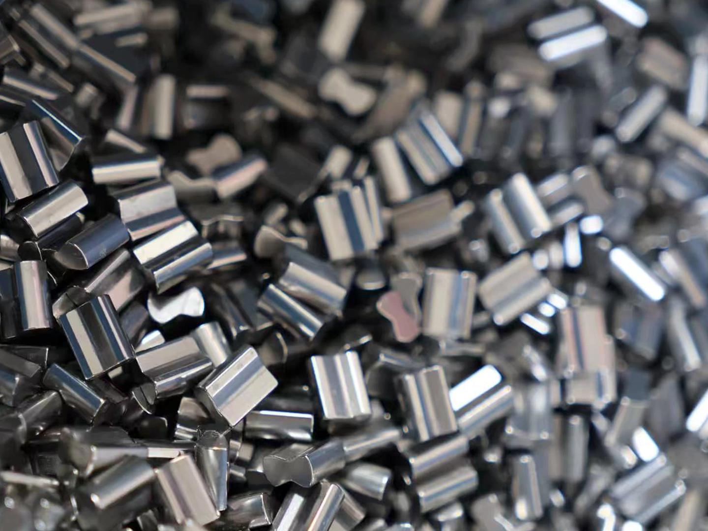
The sprag elements themselves are precision-machined from vacuum-degassed SAE 52100 high-carbon chromium bearing steel or premium vanadium-alloyed steel. The contact profiles undergo targeted carbonitriding to develop a compressive residual stress layer that mitigates micro-pitting and scuffing.
Sprag synchronization is controlled by custom-formed energizing springs. Depending on the operating envelope, LST deploys:
- Continuous Ribbon Springs: Delivering uniform, low-hysteresis radial preload to each sprag for high re-engagement frequency in automotive stop-start cycles.
- Garter / Accordion Springs: Engineered from high-fatigue-strength stainless steel (17-7 PH) or phosphor bronze, capable of sustaining dynamic fluid shearing without fatigue crack initiation at operating temperatures from -40°C to +160°C.
3. Application-Specific Performance Specifications
Modern automatic transmissions span diverse operational domains, from the ultra-smooth shift characteristics required in luxury passenger vehicles to the continuous high-slip/high-torque cycles of forestry and earthmoving equipment. The table below delineates typical OEM-grade sprag assembly parameters across major drivetrain classifications.
| Drivetrain Segment | Target Platforms & Transmissions | Rated Torque (Nm) | Freewheel Drag (Nm @ 2500 RPM) | Overrunning Speed Limit (RPM) | Primary Cage Architecture |
|---|---|---|---|---|---|
| Heavy Off-Highway & Mining | Caterpillar, Komatsu, Volvo CE (Powershift / Stator Clutches) | 3,500 – 12,000+ | < 0.85 | 3,200 – 4,500 | Dual Heavy-Gauge Steel / Machined Bronze |
| Commercial & Transit Bus | Allison World TRT/HD, ZF EcoLife, Voith D85x/D86x | 2,200 – 5,800 | < 0.45 | 4,800 – 6,000 | Ribbon-Retained Polymer / PEEK Reinforced |
| Agricultural & Forestry | John Deere, Massey Ferguson, ZF Transmatic | 1,800 – 4,200 | < 0.50 | 3,600 – 4,800 | Dual Pressed-Steel Segmented |
| Passenger Vehicles (RWD/AWD) | Ford (10R80), GM/Chevy (10L90), Mercedes-Benz (9G-Tronic) | 650 – 1,600 | < 0.18 | 7,500 – 9,000 | Centrifugal Lift-Off Sprag (Polymer Cage) |
| Premium Passenger & Performance | Bentley, Cadillac, Jaguar, VW/Audi (ZF 8HP / 9HP Platforms) | 800 – 2,100 | < 0.15 | 8,000 – 10,200 | Ultra-Low Inertia Engineered PEEK |
For custom transmission envelopes, LST Sprag Clutch designs and fabricates assemblies matching specific radial envelopes, including non-standard shaft splines and integrated thrust-washer bearing surfaces.
4. Failure Mode and Effects Analysis (FMEA) in Torque Converter Stators
Stator freewheel assemblies operate submerged in transmission fluid contaminated with clutch friction material, oxidation by-products, and metallic particulate. Understanding primary failure dynamics allows procurement and quality engineers to evaluate supplier design verification testing (DVT) protocols.
| Failure Mode | Root Mechanical Cause | Operational Consequence | LST Sprag Clutch Engineering Mitigation |
|---|---|---|---|
| Sprag Turnover / Rollover | Excessive torque spike exceeding designed strut locking angle; housing ring dilation. | Complete loss of stall torque multiplication; vehicle cannot accelerate under load; metal fragment dispersion. | Optimized asymmetrical cam profile design; selection of case-hardened AISI 8620H steel rings with high yield strength. |
| False Brinelling / Fretting | High-frequency torsional vibrations from engine firing order while freewheeling. | Raceway surface indentation; sprags catch during freewheeling, creating parasitic heat and vibration. | Controlled carbonitriding for high compressive surface stresses; engineered spring dynamics to dampen micro-bounce. |
| Cage Rupture / Window Fracture | Excessive centrifugal acceleration forces combined with differential hydrodynamic drag. | Sprags skew out of axial alignment; catastrophic clutch lockup in both forward and reverse directions. | Transition from brittle polyamides to carbon-fiber-reinforced high-temperature polyphthalamide or stamped steel cages. |
| Glazing & Hydrodynamic Aquaplaning | Inadequate spring force to break through oil boundary film at high relative rotational speeds. | Delayed or intermittent stator engagement; transmission “shudder” or flare during vehicle launch. | Micro-textured contact edges; customized spring preload force matched to ATF operating viscosity gradients. |
5. Total Cost of Ownership (TCO) & Rebuild Economics
Procurement teams frequently face trade-offs between low-cost generic replacements and engineered OEM-grade assemblies. While a lower-tier sprag assembly may reduce initial unit Capex by 20% to 30%, its economic impact across the equipment life cycle can be profoundly negative. Review our technical guide on stator clutch rebuild and assembly to analyze teardown and overhaul procedures.
Life-Cycle Cost Modeling Over 10,000 Operating Hours
The standard L10h bearing life equation for freewheel clutches integrates dynamic load rating and effective working hours:
L10h = (106 / (60 · n)) · (C / P)p
Where C is dynamic load capacity, P is equivalent dynamic load, n is average operating speed, and p = 10/3 for roller/cam geometries. Sub-tier alloys with non-uniform carburized cases significantly reduce C, dropping calculated operational service life below target rebuild intervals.
| Cost Element | Generic / White-Label Sprag Assembly | LST Sprag Clutch OEM-Grade Assembly |
|---|---|---|
| Initial Component Capex | $45.00 | $65.00 |
| Mean Time Between Failure (MTBF) | 2,500 – 3,500 Operating Hours | 10,000+ Operating Hours (Rebuild Synchronized) |
| Unscheduled Teardown & Labor Cost | $4,500 (Transmission drop, disassembly, clean-up) | $0 (Zero mid-cycle failures) |
| Collateral Fluid & Cooler Contamination | $1,200 (Flushing, torque converter replacement) | $0 (Intact raceways and sprag bodies) |
| Lost Production / Machinery Downtime | $8,000 – $20,000 per event | $0 |
| Calculated Net 10,000-Hour Cost | $13,745.00+ | $65.00 |
By preventing unscheduled maintenance, investing in precision-ground, fatigue-tested custom torque converter components significantly lowers long-term operational costs.
6. Quality Management, Testing, and Compliance Frameworks
As an international supplier to Tier-1 automotive and heavy industrial remanufacturers, LST Sprag Clutch adheres to stringent manufacturing protocols. We ensure complete lot traceability, from raw mill heat numbers through precision grinding and final inspection.
- IATF 16949:2016 & ISO 9001:2015: Total quality management systems governing every stage of cold-forming, machining, induction hardening, and sub-assembly.
- SAE Standards Compliance: Rigorous validation under SAE J2883 (dynamic sprag fatigue testing) and SAE J1587 drivetrain diagnostic metrics.
- Advanced Material Verification: Micro-hardness depth profiling according to ASTM E384; core toughness and microstructure evaluation per ASTM E18 standards.
- Non-Destructive Testing (NDT): 100% magnetic particle inspection (MPI) and eddy current crack detection on inner and outer races prior to delivery.
- Dynamic Spin-Loss & Stall Test Rigs: Proprietary test beds evaluate static burst torque capacity, sprag lift-off RPM, and fluid drag loss at operating temperatures up to 150°C.
7. Sourcing Checklist for Transmission Engineers and Buyers
When issuing an RFQ (Request for Quotation) for replacement or newly engineered torque converter sprag assemblies, specify the following parameters to ensure optimal fit, performance, and durability:
- Geometric Envelope: Provide precise inner race OD, outer race ID, and axial width tolerances (±0.005 mm). Specify spline pitch and tooth profiles where applicable.
- Dynamic Stall Torque Requirements: State the maximum stall torque (including safety shock factors, typically 1.5× to 2.2× of continuous engine output).
- Overrunning Speed Profile: Define normal and maximum freewheeling RPM to determine whether contact-type or centrifugal lift-off sprag designs are required.
- Lubricant Specification: Identify fluid chemistry, viscosity index (e.g., TES 295, Dexron VI, Cat TO-4), and maximum operating temperatures to optimize spring tension and contact geometry.
- Cage Dynamics: Indicate presence of severe torsional vibration or high angular accelerations (> 5,000 rad/s²) requiring reinforced metallic or specialized composite cages.
- Delivery and Traceability Requirements: Define packaging requirements (anti-corrosion VCI packaging), PPAP (Production Part Approval Process) Level 3 submission, and material certification reports.
Frequently Asked Questions (FAQ)
Why choose a sprag assembly over a roller-ramp clutch in torque converters?
Sprag clutches offer significantly higher torque density within the same radial envelope. Because sprags act as variable-radius cams across a cylindrical raceway, an assembly can incorporate more engaging elements (Z) than a roller-ramp clutch, which requires individual planar ramps. Additionally, sprag assemblies achieve higher freewheeling speeds with reduced centrifugal parasitic drag, making them better suited for modern high-efficiency automatic and powershift transmissions.
What causes sprag turnover during high-stall conditions?
Sprag turnover (or rollover) occurs when the applied torque induces elastic dilation of the outer race or compression of the inner race beyond design limits. This increases the working radial gap, causing the contact angle (α) to exceed the critical friction limit (αcrit). When α exceeds this threshold, the normal clamping force drops instantly, allowing the sprag to flip over its cam profile, which can cause severe mechanical damage. LST prevents this by engineering optimized cam profiles and specifying high-yield case-hardened alloy steels.
Can LST Sprag Clutch custom-fabricate inner and outer rings for obsolete or specialized housings?
Yes. In addition to high-volume standard assemblies matching Caterpillar, Komatsu, ZF, Allison, and Ford patterns, LST specializes in low-to-medium-volume custom manufacturing. We manufacture bespoke inner and outer rings from forged alloy steels, complete with specialized spline geometries, integrated oil-feed holes, and customized mounting interfaces based on customer-supplied drawings or sample parts.
How do hydrodynamic transmission fluid additives affect sprag engagement?
Extreme-pressure (EP) additives and friction modifiers designed to eliminate clutch shudder in transmission wet packs can reduce the dynamic coefficient of friction (μ) on sprag raceways. If μ drops below the tangent of the strut angle, sprag slip will occur during launch. LST works closely with drivetrain engineers to optimize both spring preload tension and micro-finish surface textures, ensuring immediate mechanical engagement even when using low-viscosity, highly-additized transmission fluids.
Engineer Higher Drivetrain Reliability with LST Sprag Clutch
Whether you are designing a next-generation off-highway powershift transmission or sourcing durable rebuild components for heavy commercial vehicle torque converters, LST Sprag Clutch delivers the metallurgical precision, structural integrity, and documented reliability your systems require. Our application engineers work alongside your powertrain team from initial CAD design and FEA stress verification through PPAP validation and serial production.
Contact our engineering and sales department today to review your project blueprints, request a detailed technical data sheet, or receive a formal competitive quotation tailored to your OEM or remanufacturing supply line.