
A single sprag rollover inside an industrial torque converter can shut down a 400-ton mining excavator or a high-throughput distribution drivetrain in a fraction of a second. In hydrodynamic transmissions, the stator’s one-way sprag clutch is the silent fulcrum of mechanical leverage: when it locks, torque multiplication occurs; when it overruns, fluid coupling efficiency peaks. A structural failure or micro-slip in the clutch mechanism does not simply cause hesitation—it induces extreme hydraulic shear, fluid overheating beyond 150°C (302°F), stator freewheeling during launch, and total transmission breakdown.
For plant managers, transmission remanufacturers, powertrain engineers, and procurement directors, sourcing through an experienced torque converter one way sprag clutch oem manufacturer is the definitive step to eliminating catastrophic drivetrain failures. This technical guide examines the kinematics of sprag engagement, metallurgy requirements under high Hertzian contact stress, failure prevention, and engineering criteria for selecting and procuring heavy-duty automotive sprag clutches and overrunning clutches.
1. Kinematic Principles: The Stator Sprag Clutch in Hydrodynamic Transmissions
A torque converter relies on three primary hydrodynamic elements: the impeller (driven by the engine/motor), the turbine (driving the output shaft), and the stationary reaction member known as the stator. The torque converter one way sprag clutch is housed directly within the stator hub, anchored to a stationary ground shaft.
Torque Multiplication vs. Coupling Mode Dynamics
The operational lifecycle of a torque converter sprag clutch alternates between two distinct mechanical states governed by fluid vector angles:
- Stall & Acceleration Phase (Mechanical Lockup): At low turbine speeds (speed ratio < 0.85), fluid leaves the turbine blades with a reverse angular velocity component that opposes impeller rotation. This returning fluid impinges on the front faces of the stator blades, imparting a backward rotational moment. The sprag clutch immediately locks the stator against the stationary housing. By fixing the stator in place, fluid is redirected smoothly back into the impeller eye in the direction of rotation, compounding momentum and generating torque multiplication ratios typically ranging from 1.8:1 to 3.0:1.
- Coupling Phase (Freewheeling / Overrunning): As turbine speed approaches impeller speed (speed ratio ≥ 0.85 to 0.90), the fluid exit angle flattens and impinges upon the back face of the stator blades. The fluid momentum now urges the stator to rotate forward in the same direction as the turbine and impeller. At this hydrodynamic “coupling point,” the sprag clutch unlocks instantly, allowing the stator to freewheel. Freewheeling eliminates fluid turbulence and parasitic drag, turning the unit into a fluid coupling with mechanical efficiencies exceeding 90% to 95%.
Sprag Cam Geometry and Instantaneous Wedge Engagement
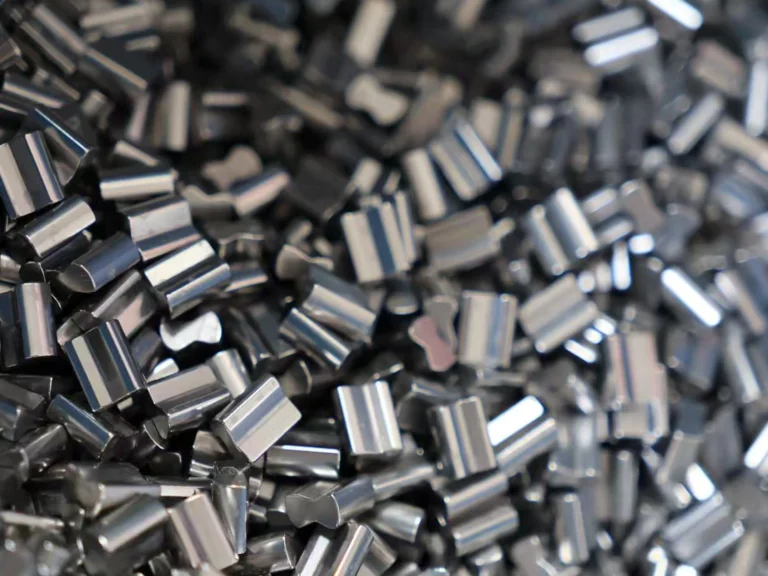
Unlike roller-ramp clutches that rely on a cylindrical roller ascending a flat machined ramp, a sprag clutch employs asymmetrical, dual-radius figure-eight cam elements positioned between concentric cylindrical inner and outer raceways. Each sprag has a minor dimension (allowing clearance when rotated one direction) and an effective major diagonal dimension that is greater than the radial distance between raceways ($h_0$).
The engagement criteria is dictated by the strut angle (α), defined as the angle between the contact force vector passing through the sprag-to-race contact point and the true normal radius line of the raceway.
Mechanical Equilibrium & No-Slip Criterion
For instantaneous, slip-free wedge action, the tangential friction force must overcome the rotational torque demand without structural slip. The fundamental condition is expressed as:
μ ≥ tan(α)
Where:
- μ = Static coefficient of friction between the bearing steel sprag cam and the hardened raceway (typically 0.08 to 0.12 in submerged automatic transmission fluid).
- α = Sprag strut contact angle (engineered between 3° and 8° depending on the cam curve profile).
If torque spikes cause radial raceway dilation such that the local gap expands and the strut angle exceeds the critical angle where tan(α) > μ, micro-slip initiates. The resulting instantaneous frictional heat and loss of wedging force lead to sprag rollover (cam inversion), causing catastrophic loss of drive.
2. Metallurgy, Heat Treatment, and Hertzian Contact Stress
Torque converter clutches operate under high compressive dynamic loads combined with cyclic shear. LST Sprag Clutch components are engineered from ultra-clean high-carbon chromium bearing steel (SAE 52100 / GCr15 / 100Cr6), providing deep core toughness, high dimensional stability, and wear resistance.
Hertzian Compressive Stress Limits
When high torque is applied, the line contacts between each individual sprag cam and the cylindrical inner and outer raceways experience extreme compressive stresses. The maximum contact pressure is calculated using the Hertzian contact formula for two contacting cylinders:
σH = √ [ (F / L) · ( (1/R1 + 1/R2) / (π · (δ1 + δ2)) ) ]
Where:
- σH = Peak Hertzian contact stress (must remain below 3,200 MPa to 3,800 MPa under maximum shock-load conditions to prevent subsurface shear yield).
- F = Applied normal force per sprag element.
- L = Effective axial contact length of the sprag cam.
- R1, R2 = Radii of curvature for the sprag cam profile and the raceway.
- δ1, δ2 = Elastic constants of the contacting bearing steel materials: (1 – ν2) / E.
Surface Metallurgy, Carbonitriding, and Finishing
To resist surface micro-pitting, scuffing, and fatigue spalling while maintaining toughness under shock loads, precision machining and heat-treating protocols are enforced:
- Core Hardness vs. Case Depth: Clutches are through-hardened or deep-case carbonitrided to deliver a surface hardness of 60 to 64 HRC, with an effective hardened case depth engineered to exceed the depth of maximum subsurface orthogonal shear stress (τ0 ≈ 0.25 · σH).
- Surface Topography: Inner and outer raceways are ground and superfinished to a mirror finish of Ra ≤ 0.2 μm (8 μin), with roundness and runout held within ≤ 0.005 mm. This minimizes initial break-in wear and stabilizes dynamic oil-wedge generation during freewheeling.
- Spring Energization Geometry: Individual sprags are held in synchronization using engineered spring cages (garter springs, expanding ribbon springs, or Z-spring clips). This ensures identical engagement angles and prevents sprag skewing under heavy torsional vibration.
3. Comprehensive Series Breakdown: Configurations and Applications
Industrial machinery and heavy vehicle automatic transmissions demand specific overrunning clutch architectures based on whether inner or outer rings are integrated, mounting arrangements, and rotational speeds. LST Sprag Clutch manufactures a broad industrial range, including series: AV, ASNU, MG, MZ, FSO, BS, TFS, DC, BWC, RSBW, CSK, HF, and HFL.
| Series Designator | Design Architecture | Bore Range (mm) | Rated Torque Range (Nm) | Max Freewheeling Speed (RPM) | Primary Industrial & Drivetrain Applications |
|---|---|---|---|---|---|
| DC Series | Cage & sprag sub-assembly without races; mounts between customer-machined shafts | 38.0 – 150.0 | 300 – 75,000 | 1,200 – 4,500 | Automatic transmissions, automotive torque converters, mining winches |
| BWC Series | Compact sprag cartridge with ribbon spring retainer; low radial profile | 12.0 – 80.0 | 50 – 4,200 | 1,800 – 6,000 | Torque converter stators, starter motor gearboxes, light powertrains |
| FSO Series | Self-contained with bearings, oil seal, integrated outer flange for torque arm | 20.0 – 150.0 | 400 – 38,000 | 750 – 2,800 | Belt conveyors, bucket elevators, high-torque industrial gear reducers |
| ASNU Series | Roller/sprag type with snap-ring outer race; non-bearing supported | 8.0 – 200.0 | 20 – 34,000 | 800 – 3,500 | Packaging machinery, textile indexing tables, light backstops |
| MG / MZ Series | Bearing-supported sprag clutch; standard keyway inner, flanged outer | 15.0 – 120.0 | 310 – 21,000 | 900 – 3,000 | Heavy agricultural drives, general machinery, industrial gearboxes |
| CSK / CSK..PP | Integrated 6200-series ball bearing dimensions; one-way sprag functionality | 8.0 – 40.0 | 2.5 – 325 | 2,500 – 10,000 | Conveyor head pulleys, printing equipment, low-torque speed reducers |
| HF / HFL Series | Drawn cup needle roller one-way clutch; thin radial wall | 3.0 – 35.0 | 0.15 – 120 | 4,000 – 15,000 | Office machines, automotive small actuators, fitness equipment |
Automotive and Heavy-Equipment Powertrain Compatibility
Automatic transmission stators operate under high rotational speeds, severe thermal loading, and rapid cycling. For specialized high-torque applications such as the 4L80E / TH400 sprag torque converter assemblies, using a multi-element sprag cage provides greater radial stability and load capacity than standard 16-element designs.
| Equipment / OEM Platform | Representative Models / Transmission Series | Clutch Mechanism Type | Torque Demand & Operating Condition |
|---|---|---|---|
| Heavy Construction & Earthmoving | Caterpillar, Komatsu, Volvo Construction | Heavy-Duty DC / BWC Sprag Elements | Extreme shock loading, forward-to-reverse shuttle shift, torque stall |
| Commercial Powertrains | Allison (Forward No.2), ZF Transmissions | Reinforced Stator Sprag Assemblies | Continuous duty cycle, high line pressures, automated lockup |
| Agricultural Tractors | John Deere, Massey Ferguson | MG, MZ & DC High-Torque Sprag Cages | Low-speed high-draft torque multiplication, PTO overrun protection |
| Passenger Cars & Light Trucks | GM (GMC, Chevrolet, Buick, Cadillac), Ford | Stator Overrunning Sprag (TH400, 4L80E, 6R80, 10R80) | High freewheeling RPM (up to 6,500 engine RPM), ATF immersion |
| European & Global Automotive | Mercedes-Benz, Volkswagen (VW), Bentley, Jaguar, Mazda | Precision High-Speed Sprag Packs | Tight radial envelopes, low drag torque requirements, low NVH |
4. Failure Modes and Root Cause Analysis in Torque Converters
Identifying the root causes of sprag clutch degradation in torque converters prevents repeat component failures in commercial fleets and field operations.
Sprag Inversion / Rollover
Sprag rollover occurs when peak engine torque coupled with hydraulic stall pressure exceeds the design holding capacity of the clutch. As torque rises, tangential reaction forces push the sprags toward their maximum camming angle. If the raceway hoop stress causes outer ring expansion or inner shaft deflection, the radial gap increases beyond design limits. The sprag cams pivot past their maximum lift height, inverting instantaneously. Once rolled, the sprags lock permanently or shatter against the cage, resulting in zero forward stator lockup. In the field, operators experience severe sluggishness during takeoff (no torque multiplication) accompanied by loud metallic grinding.
Fretting Corrosion and Brinelling
When heavy industrial machinery idles for extended periods while subjected to engine vibration, tiny oscillating micro-movements between the sprag cam and the race squeeze out the protective ATF film. This causes metal-to-metal contact, leading to false brinelling (micro-dents) and fretting corrosion. Once the raceways develop these tiny depressions, sprags stick in their pockets, resulting in delayed engagement or partial bite under load.
Centrifugal Lift-Off and Drag Torque Failures
At high freewheeling speeds during the coupling phase, centrifugal forces act on the sprags. Depending on whether the inner or outer race overruns, sprags are engineered for either “contact engagement” or “centrifugal lift-off”:
- Lift-Off Sprags: Centrifugal force pivots the sprag balance center away from the race at a predetermined lift-off speed (typically 800 to 1,200 RPM overrunning). This eliminates physical contact, yielding zero mechanical wear and zero drag torque during high-speed cruise.
- Contact Sprags: If lift-off is miscalculated or continuous contact sprags are applied at excessive overrunning speeds, hydrodynamic drag creates localized temperatures exceeding 200°C. This cooks the surrounding transmission oil, anneals the sprag contact faces (reducing hardness below 58 HRC), and causes rapid surface fatigue spalling.
5. Total Cost of Ownership (TCO) & Procurement Sourcing Guide
Purchasing teams often evaluate sprag clutches solely on initial component cost. In heavy industrial and commercial automotive operations, however, acquisition cost represents less than 5% of the total cost of ownership over a powertrain’s lifecycle.
| Cost Element | Low-Tier / Non-Certified Sourcing | OEM-Spec Precision Sourcing (LST Sprag Clutch) |
|---|---|---|
| Initial Purchase Price (CapEx) | Low (Baseline) | +15% to +25% initial investment |
| Lead Time & Inventory Cost | 8 – 14 weeks from overseas traders; high safety stock buffer required | Standard products in stock; 1-week lead time for expedited turnaround |
| Unscheduled Downtime (OpEx) | High risk; catastrophic rollover leads to complete transmission teardown | Zero-defect manufacturing; eliminates premature stator strip-downs |
| Fluid & Thermal Protection | Frequent micro-slipping increases heat; accelerates ATF breakdown | True hydrodynamic wedging; maintains proper operating fluid temperatures |
| Service Life Expectancy | 2,500 – 4,000 Operating Hours | 12,000 to 20,000+ Operating Hours under scheduled maintenance |
Engineering Sourcing & Procurement Checklist
Before issuing a purchase order for torque converter sprag clutches, powertrain procurement teams should review this five-step engineering checklist:
- Calculate Peak Operating Torque Demand:
Tdesign = Tengine_max · Rstall · Sf
Where Rstall is the converter stall ratio (e.g., 2.2) and Sf is the application dynamic service factor (minimum 1.5 for industrial conveyors, 2.0 for heavy earthmoving). Verify that the rated holding torque of the clutch exceeds Tdesign. - Verify Raceway Tolerances and Deflection Limits: Request the allowable outer race radial expansion and inner shaft runout specifications. Shaft taper and runout must not exceed 0.008 mm to ensure parallel contact across the full width of the sprag cam.
- Confirm Fluid & Additive Compatibility: Ensure clutch metallurgy and spring materials are compatible with the operating fluid (e.g., standard Dexron/Mercon ATF, Cat TO-4, Allison C4, or synthetic gear oils with extreme pressure / EP additives). Certain EP sulfur-phosphorus additives reduce friction too aggressively, preventing the sprags from biting.
- Request Non-Standard Customization Feasibility: When retrofitting legacy stators or proprietary transmission hubs, confirm the OEM manufacturer can fabricate custom inner and outer rings with non-standard dimensions.
- Verify Quality Control and Sample Availability: Insist on CMM dimensional validation, core and surface hardness test documentation, and sample availability (LST Sprag Clutch provides pre-production samples with freight collect) before full production release.
6. Quality Assurance and Standards Compliance
Industrial drivetrains are held to rigorous international standards. OEM-tier clutches are manufactured to comply with:
- ISO 9001:2015: Quality management systems covering precision machining, CNC grind paths, and assembly clean-room conditions.
- DIN 6885 / AGMA Standards: Precise keyway, spline, and press-fit tolerances for secure torque transmission on driven shafts.
- ASTM E18 & E384: Rockwell and micro-indentation hardness testing verifying 60–64 HRC case limits without surface decarburization.
- Non-Destructive Testing (NDT): 100% magnetic particle inspection on critical sprag cages to prevent micro-cracks from propagating under cyclic torsional shock loads.
Frequently Asked Questions (FAQ)
Why does a torque converter fail to multiply torque if the sprag clutch slips?
For torque multiplication to occur, fluid returning from the turbine must be physically redirected into the impeller by a stationary stator. If the sprag clutch slips or inverts, the stator spins backwards under fluid force. Without a locked stator to alter fluid vector angles, the returning oil counteracts impeller rotation, dropping the torque ratio to 1:1 or less. The engine will rev, but the vehicle or machine will struggle to accelerate from a stop.
What is the difference between a roller-ramp clutch and a sprag-type one-way clutch?
A roller-ramp clutch utilizes cylindrical rollers moving along flat ramp profiles. A sprag clutch uses asymmetrical figure-eight cams positioned between smooth cylindrical raceways. Sprag clutches provide significantly higher torque density because their compact geometry allows more load-bearing elements in the same radial cross-section. Additionally, sprags offer lower freewheeling drag and accommodate higher overrunning speeds via centrifugal lift-off designs.
Can LST Sprag Clutch supply custom non-standard sizes for specialized stators?
Yes. While standard series (such as DC, BWC, ASNU, FSO, MG, and CSK) are kept in stock, LST Sprag Clutch manufactures custom non-standard sizes. Inner and outer rings can be fabricated with custom splines, external keyways, or non-standard radial thicknesses to meet unique customer specifications. Standard products are maintained in stock for rapid dispatch, with production lead times averaging one week on standard runs.
How are evaluation samples provided to engineering and procurement teams?
To support design validation and transmission remanufacturing fit-checks, product samples can be provided with freight collect. This allows your engineering team to verify dimensional fit, surface finish, hardness, and dynamic lockup performance in your test fixture prior to placing full production orders.
Upgrade Your Powertrain Reliability with LST Sprag Clutch
Eliminate transmission stall failure, stator rollover, and expensive machine downtime. Partner directly with an experienced torque converter one way sprag clutch oem manufacturer. Explore our high-durability automotive sprag clutch line, inquire about our 1-week lead time on standard series (AV, ASNU, MG, MZ, FSO, BS, TFS, DC, BWC), or request an evaluation sample for your transmission development program today.