

In continuous-duty industrial drivetrains, mechanical failure is rarely subtle. When a high-capacity inclined conveyor experiences backstop failure, or when a high-inertia secondary drive misaligns during an overrunning cycle, the outcome ranges from catastrophic gearbox shearing to personnel hazards and crippling operational downtime. Power transmission engineers face a persistent challenge: off-the-shelf freewheel units often fail to meet demanding envelope constraints, aggressive thermal profiles, or dynamic torque spikes. Sourcing a custom one way cam clutch OEM is not merely about sourcing a component; it is an architectural decision to protect mechanical assets, eliminate rotational backlash, and optimize system-level mechanical efficiency.
A cam clutch—frequently designated in mechanical engineering literature as a sprag freewheel or sprag clutch—is an angular, mechanical non-reversal mechanism that transmits radial torque in one direction while freewheeling freely in the opposite direction. By utilizing precision-profiled cam sprag elements rather than cylindrical rollers or mechanical pawls, these clutches deliver superior torque density, near-zero mechanical backlash, and high dynamic engagement response. This engineering guide outlines the functional mechanics, mathematical sizing frameworks, metallurgical controls, and total cost of ownership (TCO) benchmarks required for specifying and sourcing custom cam clutches from LST Sprag Clutch.
1. Working Kinematics: Sprag Cam Geometry and Friction Interfaces
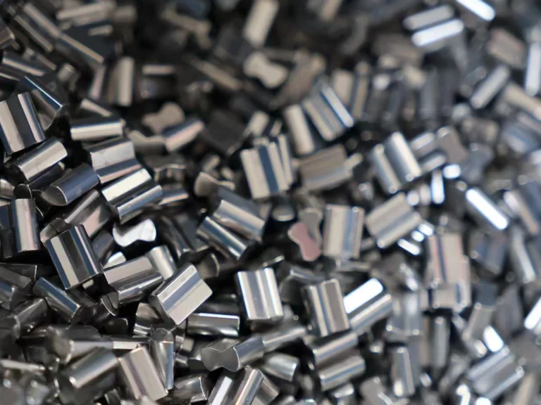
The operational reliability of an overrunning clutch depends on the kinematic profile of its internal locking elements. While conventional roller-ramp clutches use cylindrical rollers acting on inclined planar ramps, a cam clutch integrates asymmetrical, precision-ground cam sprags positioned annularly between concentric inner and outer races.
Figure 1: Cam sprag contact mechanics showing wedge angle (α) relative to inner and outer race vectors.
The Physics of Sprag Wedge Mechanics
A cam sprag acts as a variable-diameter strut. The cross-sectional profile possesses two distinct radii: a transverse dimension smaller than the annular gap between the races, and a diagonal dimension larger than that gap. The sprags are maintained in constant readiness via continuous energizing spring systems—typically circular garter springs, individual leaf springs, or expander bands.
When relative rotation between the races occurs in the driving direction, the sprags tilt and wedge themselves between the races via frictional adhesion. Mechanical lockup is governed by the equilibrium of tangential and normal forces. For slip-free engagement without instantaneous micro-skidding, the cam profile must satisfy the fundamental wedge condition:
tan(α) ≤ μ
Where:
- α (Alpha) is the dynamic wedging angle (strut angle) formed between the contact point normal and the radial vector of the race.
- μ (Mu) is the static coefficient of friction at the lubricated metal-to-metal boundary layer (typically 0.08 to 0.14 under boundary-lubricated conditions).
If the operational torque drives the sprag to an angle where tan(α) > μ, dynamic slippage will occur, causing rapid localized flash heating, adhesive galling, and catastrophic surface wear. High-performance custom OEM clutches employ a varying cam profile design (progressive curvature) where the wedge angle remains tightly controlled throughout the entire range of manufacturing tolerances and radial elastic deflections.

Three Primary Functional Modes
Custom cam clutches are engineered around three main operational kinematics:
- Overrunning: One race rotates at operational speed while the other race remains stationary or rotates at a lower speed in the same direction. When relative speed reverses, the clutch disengages automatically. Applications include dual-motor gear drives and starter motor disconnects.
- Backstopping (Non-Reversal): One race is rigidly coupled to the machine frame. The shaft turns freely in the functional forward direction. Instantaneous reverse rotation triggers mechanical lockup, preventing gravitational rollback in inclined conveyors, bucket elevators, and pump systems.
- Indexing: Reciprocating mechanical motion applied to one race translates into intermittent, uni-directional stepped rotation of the driven race. Used in high-precision indexing feeds, packaging lines, and metal stamping machinery.
2. Comparative Kinematics: Sprag Cam vs. Alternative Freewheels
Selecting the optimal power transmission topology requires comparing the structural and performance profiles of modern freewheel variants. The table below outlines how custom sprag freewheels compare to standard market configurations.
| Mechanical Characteristic | Custom Sprag / Cam Clutch | Roller-Ramp Clutch | Wrap Spring Clutch | Ratchet and Pawl |
|---|---|---|---|---|
| Torque Density (Nm/cm³) | Extremely High (> 45 Nm/cm³) | Moderate (20 – 30 Nm/cm³) | Moderate to High | Low |
| Backlash / Engagement Lag | Near-Zero (Instantaneous) | Low to Moderate (2° – 5°) | Moderate (Dynamic windup) | High (Pitch-dependent) |
| Maximum Overrunning Speed | High to Extreme (with Lift-off) | Moderate | Low (< 1,000 RPM) | Very Low (< 300 RPM) |
| Dynamic Shock Load Capacity | High (Multi-sprag load sharing) | Moderate (Prone to ramp brinneling) | Low (Prone to fatigue fracture) | High (Single tooth load) |
| Vibration & Torsional Damping | Superior (Elastomeric response) | Low | Poor (Resonance risks) | None |
| OEM Envelope Adaptability | Exceptional (Custom raceways/bores) | Restricted by ramp geometry | Low dimensional flexibility | Bulky |
3. Engineering Sizing Calculations: Mathematical Rigor for Procurement
Undersizing an overrunning clutch leads to premature fatigue spalling, sprag turnover, and catastrophic rollback. Sizing must account for motor nominal power, dynamic inertia, starting current dynamics, and real-world industrial shock loads.
Nominal Torque Calculation
To establish baseline operational torque from input motor characteristics, apply the primary mechanical drivetrain equation:
Tnom = (9550 × P) / n
Where:
- Tnom = Nominal driving torque in Newton-meters (Nm)
- P = Input driver rating in kilowatts (kW)
- n = Rotational velocity in revolutions per minute (RPM)
Design Torque and Service Factors
To calculate the required minimum design torque (Tdes) for custom OEM manufacturing, apply an empirical operational service factor (Ks) alongside acceleration/deceleration peak coefficients:
Tdes = Tnom × Ks × Ktemp × Kindex
Where:
- Ks = Baseline service factor based on prime mover and load type:
- Electric motor with smooth, steady continuous load (centrifugal pumps, blowers): 1.5 – 2.0
- Reciprocating compressor, ball mills, heavy shock load conveyors: 2.5 – 3.5
- High-inertia dual-drive system with direct-on-line (DOL) start: 3.5 – 4.5
- Ktemp = Thermal derating factor (1.0 for ambient temperatures ≤ 50°C; 1.25 for 51°C to 80°C; 1.5 for > 80°C).
- Kindex = Dynamic factor for indexing applications (typically 1.3 to 2.0 depending on cycle frequency f > 150 cycles/min).
Centrifugal Sprag Lift-Off Speed ($n_{lo}$)
For high-speed overrunning applications, friction, wear, and parasitic drag can be reduced by using non-contact lift-off sprags. When the inner or outer race exceeds a critical angular velocity, centrifugal force overcomes the energizing spring tension, causing the sprags to swing out of contact with the raceway.
nlo = √( Fspring / (msprag × rcg × cos(θ)) )
Where msprag is sprag unit mass, rcg is the radius to the center of gravity, and Fspring is the pre-load tension. In lift-off configurations, wear on the contact surfaces drops to zero during continuous overrunning, extending the clutch’s operating life.
Figure 2: Engineering cross-section of an integrated LST custom one-way cam clutch showing bearings, seal paths, and raceway clearances.
4. OEM Customization Parameters: Mechanical and Environmental Options
Standard catalog units frequently compromise packaging density, seal integrity, or shaft mounting reliability. A dedicated custom one way cam clutch OEM partner such as LST Sprag Clutch Products enables machine builders to integrate proprietary interfaces directly into the freewheel architecture.
| Subsystem / Parameter | Standard Catalog Limitations | LST Custom OEM Specification Range |
|---|---|---|
| Bore Diameters & Fits | Standard imperial/metric steps (H7 only) | Custom tolerances (m6, k6, j6), splines (DIN 5480, ANSI B92.1), tapered bores, shrink-fit interfaces |
| Sprag Kinematic Profiles | General-purpose curvature | Non-rollover designs (engineered stop wings), centrifugal lift-off (inner or outer race lift-off) |
| Integrated Bearing Support | Often requires external bearings | Direct incorporation of deep groove, angular contact, or cylindrical roller bearings within the clutch envelope |
| Housing & Flanges | Foot-mount or bare cartridge only | Custom torque arms, multi-bolt pattern flanges, piloted spigots, gearbox end-cover integration |
| Sealing Mechanisms | Standard NBR double-lip seals | Labyrinth non-contact seals, reinforced FKM (Viton) for high temperatures, extreme dust exclusion scrapers |
| Lubrication Architecture | Pre-greased or basic splash oil | Forced-circulation oil ports, dry-film MoS2 coatings for boundary states, food-grade NSF H1 lubricants |
Advanced Metallurgy and Heat Treatment Protocols
The service life of a sprag freewheel is fundamentally tied to the contact fatigue strength of its inner and outer raceways. Under heavy engagement, local Hertzian contact stresses can exceed 2,200 to 3,000 MPa. LST Sprag Clutch uses high-purity, vacuum-degassed bearing and carburizing alloys to resist these loads:
- Raceway Metallurgy: Precision-machined from 100Cr6 (SAE 52100) or high-grade carburizing alloy steels (such as 20CrNiMo / SAE 8620).
- Thermal Processing: Controlled atmosphere carburizing or carbonitriding achieves an effective surface hardness of 60 to 64 HRC, with a case depth tailored between 0.8 mm and 2.2 mm. This process leaves a ductile, shock-absorbing core (hardness 32 to 40 HRC) to absorb high torsional spikes without brittle fracture.
- Surface Finish: Contact raceways undergo micro-finish super-finishing to an arithmetic roughness of Ra ≤ 0.2 μm, minimizing frictional micro-welding and mechanical wear during overrunning.
5. Application Engineering: Conquering High-Stakes Drivetrains
Figure 3: Heavy-duty backstop cam clutch installed on an industrial conveyor drive to prevent reverse runaway.
Inclined Bulk Handling Conveyors and Bucket Elevators
In overland conveyor networks handling bulk materials, a drive trip stops the forward input power instantly. Gravity attempts to drive hundreds of metric tons of material backward. An undersized or slow-engaging backstop allows reverse acceleration to develop; when the unit finally attempts to bite, the shock load can rupture the gear teeth or tear the drive base from its moorings.
By selecting a custom-engineered backstop cam clutch with dynamic load capacities up to 500,000 Nm, plant operators protect their drivetrains. Zero-backlash engagement arrests the shaft immediately upon motor shutdown, dissipating elastic energy through structural torque arms equipped with engineered dampening dampeners.
Redundant Dual-Motor and Emergency Pony Drives
Large ventilation fans in mining and industrial kilns require non-stop rotation. Drivetrains typically utilize a primary high-power AC motor paired with a lower-speed auxiliary “pony” motor. A custom overrunning clutch mounted on the intermediate shaft allows the secondary drive to accelerate and overrun the primary motor automatically during startup, maintenance, or primary motor failure—preventing motor burn-out without manual clutching.
High-Frequency Mechanical Indexing Machinery
Packaging, converting, and sheet-metal stamping lines frequently rely on mechanical link-arm drives to convert constant rotary motion into incremental step feeds. Cam clutches built with lightweight sprags and high-stiffness leaf springs handle cycle frequencies exceeding 300 to 600 indexes per minute with angular positioning repeatable to within arcminutes.
6. Total Cost of Ownership (TCO) vs. Procurement Capital Cost
Procurement teams are often pressured to purchase standard off-the-shelf industrial clutches to lower upfront capital expenditure (CapEx). However, evaluating the Total Cost of Ownership (TCO) over a standard 5-year operating window reveals a different economic picture. Standard catalog clutches that require auxiliary bearings, external lubrication modifications, or frequent replacement generate significantly higher operational expenditure (OpEx).
| Life-Cycle Cost Element | Standard Commodity Freewheel | LST Custom Engineered OEM Cam Clutch |
|---|---|---|
| Initial Purchase Price (CapEx) | Baseline ($) | 15% – 35% higher ($$) |
| Engineering & Adaptor Cost | High (Requires custom sleeves, spacers) | Zero (Engineered to native envelope) |
| Installation & Alignment Labor | 4 – 8 hours (Critical shaft alignment) | 1 – 2 hours (Drop-in assembly) |
| Unplanned Downtime Risk | Moderate to High (Prone to wear/slip) | Negligible (Optimized metallurgy & design) |
| Lubricant Maintenance Intervals | Every 500 – 1,000 operating hours | 5,000+ hours (or Sealed-For-Life) |
| 5-Year Replacement Frequency | 2 to 4 units replacement typical | Single unit sustained operation |
| Net 5-Year Ownership Cost | Significantly Higher (Up to 3-5x CapEx) | Optimized (Lowest Net Asset Cost) |
The 10-Point Engineering Sourcing Checklist
Before issuing an RFQ for a custom one way cam clutch, review these mechanical design parameters:
- Torque Verification: Calculate both maximum continuous running torque and peak dynamic stall torque.
- Overrunning Speed Envelope: Identify which race (inner vs. outer) overruns, and confirm maximum operational RPM relative to calculated lift-off speeds.
- Directionality: Define freewheeling direction (clockwise vs. counter-clockwise) looking from the designated reference face.
- Shaft Interface Tolerances: Specify keyway (DIN 6885/1, US standard), spline geometry, shrink disc, or press fit.
- Concentricity and Alignment: Confirm radial runout (TIR ≤ 0.05 mm) and angular alignment limitations between the mating shafts.
- Bearing Strategy: Determine whether external support bearings exist or if internal bearing integration is required within the clutch housing.
- Environmental Conditions: Document operating temperatures, exposure to abrasive dust, moisture, corrosive agents, or washdown chemicals.
- Lubrication Architecture: Choose between sealed lifetime grease, oil-bath dip, or continuous oil-mist/forced feed circulation.
- Regulatory and Safety Frameworks: Check requirements for ASME B20.1 (safety for conveyors), OSHA 1910 mechanical power transmission standards, or European CE Machinery Directive compliance.
- Predictive Maintenance: Determine whether torque-arm load monitoring or temperature sensor tapping points are needed.

7. Technical Frequently Asked Questions (FAQ)
What causes cam sprag turnover, and how do custom designs prevent it?
Sprag turnover occurs when an extreme overload causes the sprag to rotate past its maximum design engagement angle. Once flipped, the sprag wedges mechanically in reverse, locking the clutch in both directions or shattering the internal energizing cage. Custom OEM clutches from LST prevent this by using non-rollover cam profiles. These sprags include integrated mechanical stop-wings that contact neighboring sprags during extreme overloads, creating a solid structural ring that resists further rotation without turnover.
Can standard extreme pressure (EP) lubricants be used in a cam clutch?
No. Standard extreme-pressure (EP) industrial oils containing solid friction modifiers such as molybdenum disulfide (MoS2), graphite, or high-potency zinc anti-wear additives should not be used in friction-dependent cam freewheels. These additives form a low-shear lubricating film that reduces the friction coefficient below the critical threshold (μ < tan α). This causes the sprags to slip dynamically during torque application, damaging the raceways. Use only uninhibited mineral oils, approved turbine oils, or manufacturer-specified freewheel greases.
How does shaft runout and alignment affect overrunning clutch life?
Sprag clutches rely on a consistent annular space between the inner and outer races. Radial runout or angular misalignment causes uneven load distribution among the sprags. Under excessive runout (typically > 0.08 mm Total Indicator Reading), individual sprags absorb disproportionate shock forces during engagement, while other sprags sit unloaded. This concentrated stress leads to fatigue spalling, cage fracture, and premature failure. Custom units often integrate internal precision bearing sets to control runout across the mating raceways.
What typical lead times are associated with custom OEM sprag freewheels?
Standard modifications—such as custom bore diameters, modified keyways, or specific mounting flanges—typically ship in 3 to 5 weeks. Clean-sheet designs that require custom forging dies, specialized cam profiles, or unique metallurgy run on an engineering prototype timeline of 8 to 12 weeks, followed by production delivery backed by PPAP and ISO 9001:2015 quality documentation.
Partner with LST Sprag Clutch for Your Custom Drivetrain Solutions
Engineering robust industrial machinery requires zero tolerance for drive slippage or catastrophic reverse runaway. As a specialized engineering and manufacturing partner, LST Sprag Clutch provides custom-engineered one-way cam clutches, backstops, and overrunning freewheels built to match your performance envelope and duty cycles. Our team works directly alongside your engineering group from initial kinematic analysis and finite element stress modeling through to metallurgical finishing and production.
Protect your drivetrains, optimize your power density, and reduce lifecycle downtime. Explore LST Custom Cam Clutch Configurations and connect with our application engineers today to discuss your OEM specifications.