In high-torque industrial powertrains, an off-the-shelf overrunning clutch with standard imperial or metric bores often introduces severe engineering compromises. Forcing a standard-bore clutch onto a legacy drive shaft or non-standard gearbox output shaft using adapter sleeves, stepped shafts, or field-machined bushings introduces radial runout, amplifies torsional vibration, and creates stress concentrations. In critical installations such as bulk material handling conveyors, industrial fan drives, and heavy gearboxes, mechanical drive failure does not simply mean a blown component—it risks catastrophic backdrive, unconstrained material rollback, personnel injury, and thousands of dollars per hour in unscheduled plant downtime.
As a specialized custom bore cam clutch manufacturer, LST Sprag Clutch designs and fabricates precision-engineered freewheel assemblies built to exact shaft interfaces. Whether you require an oversized bore cam clutch to fit high-diameter hollow shafts without stepping down your shaft diameter, or a high-precision splined profile for automated indexing machinery, custom bore engineering guarantees optimal load distribution, minimal runout, and extended Mean Time Between Failures (MTBF). This comprehensive guide details the mechanical kinematics, bore sizing criteria, lubrication profiles, and Total Cost of Ownership (TCO) considerations essential for plant managers, mechanical engineers, and procurement directors sourcing mission-critical one-way clutches.

Custom Bore Cam Clutch Manufacturer Kinematics & Operating Principles of Cam Sprag Clutches
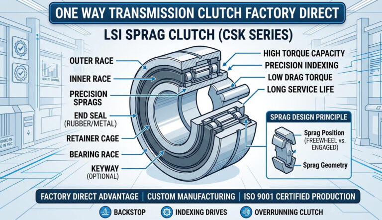
A cam clutch—frequently designated as a sprag freewheel clutch—is an automatic mechanical drive element that transmits torque via frictional wedging in one direction of relative rotation, while permitting unrestricted freewheeling in the reverse direction. Unlike pawl-and-ratchet mechanisms that suffer from backlash and discrete locking points, a cam clutch sprag type manufacturer utilizes precision-profiled sprag cams situated in an annular space between concentric cylindrical inner and outer races.
The core components and kinematics of a heavy-duty cam clutch include:
- Precision Sprags (Cam Elements): Individually contoured asymmetric cams manufactured from high-grade chromium steel (such as AISI 52100 or carburized SAE 8620) hardened to 58–62 HRC. The cam’s geometry features variable contact angles that optimize the balance between instantaneous gripping capability and continuous freewheeling wear resistance.
- Energizing Springs: Ribbon springs, garter springs, or individual leaf springs apply continuous radial pre-load against the sprags. This keeps the sprag surfaces in micro-contact with both inner and outer races, enabling zero backlash and instantaneous torque take-up when rotation reverses.
- Inner and Outer Races: Precision-ground races with surface finishes controlled to Ra ≤ 0.4 μm (16 μin). The races must withstand extreme Hertzian contact stresses, which regularly exceed 2,000 to 3,000 MPa during peak shock loads.
- Centrifugal Lift-Off Designs (Optional): In high-speed overrunning applications, LST incorporates lift-off sprag technology where centrifugal force at high inner-race or outer-race RPM overcomes spring tension, pivoting the sprags away from the race surface. This achieves non-contact operation, eliminating friction, heat build-up, and mechanical wear during overrunning phases. Explore our technical analysis on high-speed torque transfer in our engineering guide to stator freewheels and high-torque clutches.
Why Specify a Custom Bore Cam Clutch?
Industrial machinery builders and MRO engineers frequently confront physical envelope constraints that standard catalog components cannot solve. Specifying a customized shaft bore sprag clutch eliminates interface compromises through tailored engineering:
1. Direct Retrofitting on Legacy Shafting
Legacy processing lines built across North America and Europe often feature non-standard shaft diameters (e.g., fractions of an inch, metric-imperial hybrid sizing, or worn shafts ground undersize during prior maintenance). A precision bore cam clutch manufacturer manufactures the clutch inner ring with exact inner diameter (ID) tolerances (such as H7, G6, or custom clearance/press fits), avoiding the need to remanufacture entire drive shafts or implement failure-prone keyway shims.
2. Elimination of High-Stress Step-Down Shafts
When selecting standard clutches based purely on torque requirements, the required bore size frequently forces engineers to specify a clutch one or two sizes larger simply to match the drive shaft diameter. Conversely, turning down a thick shaft to fit a smaller standard clutch creates severe stress-raiser notches at the shoulder radius, inducing fatigue failure under cyclic bending moments. An oversized bore cam clutch maintains a compact outer diameter (OD) and torque rating while incorporating an expanded bore to seat directly on full-diameter shafts.
3. Advanced Shaft-to-Hub Interface Geometries
While standard clutches rely on single keyways conforming to DIN 6885 or ANSI B17.1, demanding cyclic or reversing loads can wallow out keyways over time. Custom bore manufacturing provides alternative drive connections:
- Dual or Staggered Keyways: Splitting dynamic torque over 120° or 180° keyways to reduce shear stresses on shaft materials.
- Involute Splines: Precision internal splines conforming to ANSI B92.1, DIN 5480, or JIS D 2001, providing superior load sharing across multiple teeth for indexing drives.
- Integrated Keyless Locking Assemblies (Shrink Discs / Taper Sleeves): For high-runout sensitivity and zero-backlash mounting without cutting stress-inducing keyseats into hardened shafts.
Engineering Specifications & Comparative Performance Data
Selecting the right transmission component requires matching mechanical capabilities against operational duty cycles. Below are detailed comparative parameters for engineered cam clutches.
Table 1: Standard Catalog vs. Custom Bore Cam Clutch Engineering
| Design Parameter | Standard Off-the-Shelf Cam Clutch | LST Custom Bore Cam Clutch |
|---|---|---|
| Bore Sizing Range | Fixed metric (10–150 mm) or imperial (0.5″–5.0″) increments | Fully customizable (12 mm to 450+ mm, intermediate & decimal sizes) |
| Bore Machining Tolerance | Standard ISO H7 or H8 fit | Precision ISO H6, G6, k6, or customer-specific micro-tolerances |
| Shaft Locking Interface | Single keyway (DIN 6885/1 or ANSI B17.1) | Single/dual keyways, spline profiles (DIN 5480, ANSI B92.1), or hydraulic press fit |
| Material Specification (Inner Race) | Standard bearing steel (AISI 52100) | Case-hardened alloys (SAE 8620, 20CrMo, 18CrNiMo7-6) with deep case depth (1.2–2.0 mm) |
| Sealing Mechanisms | Standard NBR single-lip contact seals | Viton double-lip, PTFE labyrinth non-contact, or heavy-duty grease purge taconite seals |
| Shaft Runout Tolerance (TIR) | ≤ 0.05 mm (0.0020″) | ≤ 0.015 mm (0.0006″) for high-speed dynamic balance |
Table 2: Operational Modes & Application Matrix
Cam clutches operate across three primary functional categories. The internal sprag geometry, spring balance, and lubrication strategy differ dramatically across each mode.
| Functional Mode | Operational Kinematics | Primary Industrial Application | Critical Engineering Metric |
|---|---|---|---|
| Overrunning (Freewheeling) | Clutch engages to transmit power from a prime mover, then freewheels when driven machine overspeeds or auxiliary drive kicks in. | Dual-drive fans, multi-motor pump drives, dual genset starters, industrial turbine barring gear. | Maximum Overrunning Speed (RPM), Drag Torque (N·m), Heat Dissipation Rate. |
| Backstopping (Anti-Rollback) | Clutch overruns continuously during forward operation; instantly wedges to lock reverse rotation when drive motor de-energizes. | Inclined belt conveyors, bucket elevators, steep angle aggregate elevators, skip hoists. | Peak Static Holding Torque (N·m), Instantaneous Lock Response Time (<10 ms). |
| Indexing (Intermittent Feed) | Reciprocating linear or oscillating rotary motion is converted into stepped, unidirectional intermittent rotational advancement. | Packaging index tables, sheet metal punching feeds, printing presses, textile feed rollers. | Index Frequency (Cycles/Min up to 1,200 CPM), Backlash (<0.05°), Index Pitch Accuracy. |
Torque Sizing Formulas & Mechanical Calculations
Undersizing a cam clutch results in accelerated sprag flatting, race brinelling, and early slippage. Oversizing wastes capital budget and increases drag torque. When designing a custom torque cam clutch, engineering calculations must account for steady-state operating torque, prime mover dynamics, and severe shock load factors.
1. Nominal Operating Torque Calculation
To determine basic operating torque ($T_{nom}$) from mechanical input power:
T_nom (lb-ft) = (HP × 5252) / RPM
T_nom (N·m) = (kW × 9550) / RPM
2. Design Torque Requirement with Dynamic Service Factors
Actual design torque ($T_{design}$) must integrate a composite Service Factor ($SF$) based on prime mover pulsation and driven load characteristics:
T_design = T_nom × SF
Service factors typically range from:
- SF = 1.2 to 1.5: Uniform electric motor drives with low-inertia steady-state loads (e.g., continuous centrifugal fans, smooth centrifugal pumps).
- SF = 2.0 to 2.5: Electric motor driving non-uniform loads with moderate shock (e.g., bucket elevators, general industrial conveyors, rotary kilns).
- SF = 3.0 to 4.5+: Internal combustion engine drives or heavy shock, reciprocating, and reversing loads (e.g., jaw crushers, vibratory screens, reciprocating compressors).
3. Heat Dissipation and Overrunning Power Loss
During extended overrunning phases, sprag contact drag creates frictional heat that must not exceed the lubricant’s oxidation thermal limits. Power loss ($P_{loss}$) in the freewheeling phase can be calculated using clutch drag torque ($T_{drag}$):
P_loss (Watts) = (T_drag [N·m] × ω [rad/s])
Where: ω = (2 × π × N_overrunning) / 60
If continuous overrunning peripheral speed exceeds 15 m/s (3,000 ft/min), engineers must utilize centrifugal lift-off sprag elements or circulating oil lubrication systems to maintain internal sump temperatures below 85°C (185°F).
Lubrication, Sealing & Environmental Protection
Lubrication dynamics govern the operational lifespan of any sprag freewheel. The friction coefficient between sprags and races must be strictly maintained: too high results in rapid surface abrasive wear; too low causes sprags to slip rather than grip when torque is demanded.
Lubrication Selection Criteria
- Lubricant Additive Warning: Never use Extreme Pressure (EP) lubricants containing solid anti-friction friction modifiers such as molybdenum disulfide ($MoS_2$), graphite, or zinc dithiophosphate additives. These friction modifiers lower the dynamic coefficient of friction below the critical wedging angle, preventing the sprags from properly engaging and causing catastrophic dynamic slippage.
- Oil Lubrication (Preferred for High Speeds): Low-viscosity turbine oils (ISO VG 32 to VG 68) with anti-foaming and anti-oxidation inhibitors provide maximum heat removal. Required for high-cycle indexing and continuous overrunning at elevated RPM.
- Grease Lubrication (Ideal for Enclosed Drives / Low Maintenance): Semi-fluid or NLGI #1 or #2 lithium-soap greases without EP additives are suitable for backstop applications and lower-speed conveyor shafts. Grease retention saves operational overhead where routine relubrication is challenging.
Engineered Sealing Solutions
As a seasoned industrial cam clutch supplier, LST equips custom bore assemblies with sealing configurations tailored to severe operating environments:
- Double-Lip Viton (FKM) Seals: Engineered for elevated operating temperatures up to 200°C (392°F) and chemical exposure to synthetic lubricants.
- Non-Contact Labyrinth Seals: Critical for ultra-high-speed freewheeling where lip seal friction generates unmanageable parasitic drag and premature thermal failure.
- Taconite Heavy-Duty Purge Seals: Designed for mining, cement, and bulk material handling where fine aggregate dust and slurry degrade internal components.
For more commercial applications and volume distribution options, review our one-way sprag clutch wholesale solutions.
Compliance, Safety Codes & Quality Standards
Heavy mechanical power transmission systems operate under stringent regulatory mandates. Installing an under-engineered backstop or freewheel can directly trigger plant safety non-compliance. LST manufactures custom bore cam clutches under strict adherence to North American and international industrial standards:
- OSHA 1910.219 (Mechanical Power-Transmission Apparatus): Compliance with guarding, shaft projection safety, and fail-safe mechanical backstopping on vertical or inclined material transport.
- AGMA 6013 / AGMA 6113: Sizing and installation standards for industrial enclosed gear drives, ensuring torque ratings and shaft fit tolerances align with heavy-duty gearbox practices.
- ANSI / ASME B17.1 & DIN 6885: Strict machining tolerances for single and multiple parallel keyways, avoiding stress cracks and hub split failures.
- ISO 9001:2015 Quality Certification: Total quality management governing metallurgical batch verification, 100% magnetic particle inspection (MPI) for race crack detection, and coordinate measuring machine (CMM) dimensional validation on every custom bore.
- MSHA (Mine Safety and Health Administration): Heavy-duty, spark-free, fail-safe backstopping compliance for underground coal and aggregate conveyor systems.
Stay updated on regulatory and technological advancements in our industrial mechanical drive news section.
Total Cost of Ownership (TCO): Custom Manufacturing vs. Field Modifications
Procurement teams are often tempted by lower upfront CapEx for off-the-shelf standard clutches, intending to re-machine the bore locally or utilize bushing adapters. This strategy almost universally inflates Total Cost of Ownership (TCO) through hidden downstream failures.
Table 3: Economic Breakdown – Factory Custom Bore vs. Third-Party Machine Shop Rework
| Cost & Performance Factor | Standard Off-the-Shelf + Local Machine Shop Rework | LST Factory-Engineered Custom Bore Clutch |
|---|---|---|
| Initial Component CapEx | Moderate (Catalog Unit Cost) | Moderate-High (Engineered-to-Order) |
| Secondary Machining Cost | $300 – $800 (EDM wire cutting or grinding hardened inner race) | $0 (Included in factory supply) |
| Metallurgical Integrity Risk | High: Machining through the case-hardened layer exposes ductile soft core steel; local heat causes micro-cracking and loss of temper. | Zero: Bore is fully machined, splined, or keyed prior to controlled deep case carburization and finish grinding. |
| Shaft Runout (TIR) Alignment | 0.06 – 0.12 mm (Frequent clamping chuck runout in job shops) | ≤ 0.015 mm (Finished on precision CNC OD/ID cylindrical grinders) |
| Manufacturer Warranty | Voided the moment the race is altered by a third party. | Full OEM factory warranty covering materials, torque, and workmanship. |
| Downtime Risk Profile | High probability of early freewheel slippage or keyway shear. | High reliability with continuous MTBF exceeding 30,000 to 50,000+ operational hours. |
The True Cost of Freewheel Failure
Consider a 48-inch aggregate conveyor moving 1,200 tons per hour. If a field-reworked backstop clutch fails under load, permitting conveyor rollback, direct and indirect costs escalate exponentially:
- Material Spill Clean-up & Tonnage Loss: $15,000 – $35,000.
- Belt and Idler Structural Damage: $20,000 – $60,000.
- Unscheduled Production Downtime (12–24 Hours @ $5,000/hr): $60,000 – $120,000.
Investing in a factory-warranted, precision-machined custom inner diameter cam clutch eliminates thousands of dollars in hidden risk while ensuring compliance with operational safety standards.Formsprag Clutch – Overrunning Sprag Clutches
Step-by-Step OEM Procurement & Engineering Evaluation Checklist
Before issuing a Request for Quotation (RFQ) to an industrial overrunning clutch ODM or mechanical power transmission clutch maker, verify these technical parameters to streamline engineering and production lead times:
- Functional Role Definition: Clarify whether the application is overrunning, backstopping, or indexing.
- Kinematic Rotation Direction: Looking directly at the clutch bore face, specify whether engagement must occur with Clockwise (CW) or Counter-Clockwise (CCW) rotation of the inner or outer race.
- Exact Shaft Diameter & Tolerance: Provide dynamic shaft measurements (e.g., 85.00 mm +0.015/-0.000) rather than nominal dimensions.
- Keyway / Spline Geometry: Define standard key width & depth, dual key locations, or precise spline standard (e.g., DIN 5480 W 60×2×28×9g).
- Maximum Dynamic & Holding Torque: Provide continuous steady-state torque plus worst-case startup or stall torque (including electric motor locked-rotor torque multipliers).
- Continuous Freewheeling Speed (RPM): Note inner vs. outer race overrunning RPM to evaluate the need for centrifugal lift-off sprag technology.
- Environmental Operating Matrix: Specify ambient temperature range, exposure to washdown water, abrasives, or chemical atmospheres.
- Mounting Envelope Constraints: Detail allowable maximum outer diameter (OD), total axial length, and bolt pattern pitch circle diameter (PCD).
Frequently Asked Questions (FAQ)
Can we machine or bore out a standard hardened cam clutch inner race ourselves?
Machining a standard off-the-shelf cam clutch inner race in a local machine shop is strongly discouraged. The inner race of a sprag clutch undergoes case hardening or induction hardening to a depth of 1.2 to 2.0 mm at 58–62 HRC. Attempting to bore, broach, or wire-EDM this race will either compromise the hardened depth—exposing softer core metal that deforms under sprag wedging pressure—or introduce thermal micro-cracking and concentricity errors that void all OEM warranties. Bores must be fully machined prior to heat treatment and final precision finish grinding.
What is the minimum backlash in a custom bore cam clutch compared to a ratchet backstop?
Sprag-type cam clutches have practically zero backlash (<0.05° rotary displacement). Because sprags maintain continuous light contact with the inner and outer races via energizing spring preload, engagement is instantaneous the fraction of a millisecond rotation begins in reverse. Conversely, traditional pawl-and-ratchet backstops must physically slide into the next mechanical tooth, permitting several degrees of reverse rotation before locking, which generates high-impact shock loads on gear teeth and couplings.
How does shaft runout (TIR) affect cam clutch performance?
Excessive total indicated runout (TIR) between the shaft and the clutch housing forces the sprags to constantly displace radially during overrunning, leading to rapid spring fatigue, non-uniform sprag loading, premature race grooving, and seal failure. For standard overrunning operations, shaft runout must be kept within 0.025 mm (0.0010″), while high-speed indexing applications require runout under 0.015 mm (0.0006″).
Can a custom bore cam clutch be designed to handle both overrunning and high shaft misalignment?
A cam clutch by itself is an internal kinematic mechanism and cannot compensate for angular or parallel shaft misalignment without premature race brinelling. To solve drive misalignment issues, LST engineers custom bore clutches combined with integrated flexible couplings, roller chain couplings, or elastic jaw adapters. This allows the assembly to absorb thermal growth, structural deflection, and slight mounting misalignments while preserving perfect internal clutch concentricity.
Partner with LST Sprag Clutch for Engineered Power Transmission Solutions
When off-the-shelf components fail to meet high-performance driveline demands, LST Sprag Clutch provides the exact manufacturing capability, metallurgical excellence, and application engineering required by heavy industry. From replacement gearbox backstop clutches and high-capacity conveyor belt cam clutches to precision indexing assemblies, our engineering team handles custom bores, custom keyways, spline integrations, and specialized sealing options with short lead times.
Contact the engineering department at LST Sprag Clutch today to submit your dimensional drawings, shaft tolerances, and operational parameters for a rapid technical review and quotation.