
In heavy industrial powertrains, mechanical backdrive and indexing slippage are not minor maintenance inconveniences—they are critical failure events. A runaway inclined conveyor carrying 1,200 metric tons of aggregate per hour, an uncontrolled reverse spin on an induced draft fan, or timing drift in high-speed rotary packaging equipment instantly translates into catastrophic structural destruction, personnel hazards, and tens of thousands of dollars per hour in unplanned downtime. While standard press-fit freewheels rely on radial interference to transmit torque, transient peak loads and thermal expansion cycles frequently compromise friction-only fits, causing inner race spin and shaft fretting.
Specifying a custom keyway cam clutch eliminates friction-dependent torque transfer by introducing positive mechanical locking via precision-machined keyways on the inner race, outer race, or both. This technical guide provides plant managers, mechanical design engineers, and procurement specialists with the mechanical formulas, shaft tolerance standards, kinematic operating modes, and total cost of ownership (TCO) frameworks required to engineer, specify, and procure custom keyway cam clutches for heavy industrial duty.
1. Kinematic Principles: Cam Sprag Geometry vs. Alternative Freewheels
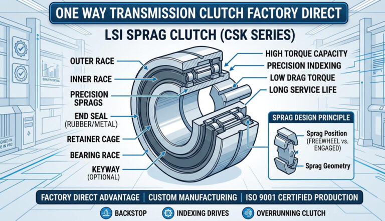
A cam clutch—frequently designated as a sprag freewheel clutch—is an overrunning, mechanical one-way transmission element. Its core architecture consists of an inner ring, an outer ring, a full complement or cage-guided assembly of asymmetrical, profiled cam sprags, and energizing springs that maintain continuous, micro-contact between the sprags and both raceways.
The Mechanics of Instantaneous Engagement
Unlike ratchet-and-pawl systems that exhibit substantial mechanical backlash while waiting for a pawl to drop into a tooth pocket, or a standard one way roller clutch bearing that relies on cylindrical rollers ascending shallow machined ramps, a cam clutch operates via cam-contour wedging:
- Driving/Engagement Direction: Relative rotation causes the asymmetrical sprags to pivot along their eccentric axis. Because the major diagonal dimension of the cam sprag is greater than the radial distance between the raceways, pivoting forces the sprags into an instantaneous wedging condition. Torque transmits across the annular gap through direct Hertzian contact stress.
- Overrunning/Freewheeling Direction: Reversing the relative rotation causes the sprags to pivot back toward their minor diagonal dimension, which is smaller than the raceway gap. The sprags slide smoothly along the outer or inner race with minimal boundary friction, sustained by a microscopic hydrodynamic or boundary lubricant film.
For applications transitioning from light-duty rolling elements, such as a drawn cup needle roller clutch or an hf series needle roller clutch, cam clutches provide drastically superior contact geometry. Roller ramps produce concentrated line contacts that deform under shock loads. In contrast, precision-machined cam profiles provide progressive engagement angles (typically between 3.5° and 8.5°), preventing contact skidding while distributing dynamic torsional loads over a significantly wider surface area.
Where miniaturized or lower-duty installations rely on an owc series one way clutch or a simple csk series one way bearing, high-demand machinery requires an engineered high torque one way clutch featuring custom inner and outer keyways to mechanically ground high dynamic shear loads directly into the drive shafts and machine housings.
2. Three Fundamental Operational Modes
Before establishing keyway dimensions and interference fits, engineers must precisely classify the clutch’s primary operational mode. Sizing formulas, heat generation thresholds, and lubrication dynamics differ substantially across these three regimes:
A. Overrunning (Freewheeling)
In overrunning mode, the clutch disengages the driven component whenever the driven shaft rotates faster than the driving shaft, or when the drive motor is de-energized. Examples include dual-motor emergency backup drives, industrial starter drives, and multi-speed creep systems.
- Inner Race Overrunning: The inner race rotates continuously at high speed while the outer race remains stationary or runs at a lower speed. Centrifugal force pushes the sprags outward against the outer race, reducing wear on the inner race.
- Outer Race Overrunning: When the outer race freewheels at elevated RPM, centrifugal force acts upon the sprags, pressing them outward against the outer raceway. If the rotational velocity exceeds the clutch’s rated lift-off speed ($n_{lift}$), aerodynamic and centrifugal forces overcome the energizing spring tension, causing the sprags to completely lift off the inner race. This eliminates frictional contact, resulting in near-zero drag torque and infinitely extended operational wear life.
B. Backstopping (Anti-Reverse)
Configured as a backstop freewheel clutch or non return clutch bearing, the outer race is anchored to the machine housing or structural foundation through a torque arm or keyway, while the inner race is keyed directly to the primary drive shaft. The clutch rotates freely in the operational direction. The moment rotation stops or power cuts out, gravitational or reverse-load forces attempt to drive the shaft backwards. The sprags wedge instantly, locking the shaft to ground with zero backlash. This function is vital for inclined belt conveyors, bucket elevators, and vertical pumps.
C. Indexing
In an indexing sprag clutch arrangement, a reciprocating linear stroke (driven by a pneumatic cylinder, eccentric crank, or hydraulic actuator) translates into intermittent, incremental unidirectional rotary motion on the output shaft. Key design criteria for indexing include instantaneous engagement response, ultra-low angular play, and dynamic spring energization to ensure index repeatability within fractions of a degree over millions of operational cycles.
3. Custom Keyway Engineering & Shaft Fitment Tolerances
The primary point of failure in retrofitted or stock freewheels operating under dynamic shock loading is not the sprag assembly itself, but the shaft-to-hub interface. Standard catalog clutches typically utilize standard clearance fits with single keyways. Under heavy reversing cycles or cyclic indexing, the keyway experiences cyclic plastic deformation, walloping, and fretting corrosion, ultimately cracking the clutch inner race.
DIN 6885.1 vs. ANSI B17.1 Custom Machining
LST Sprag Clutch manufactures inner and outer races with custom keyways precision-ground or broached to specific international standards, maintaining strict parallelism and profile concentricity:
- DIN 6885 Sheet 1 (Metric): Standard production utilizes JS9 keyway width tolerances for standard fitment, or P9 interference width tolerances for heavy reversing and indexing applications to eliminate rotational backlash at the keyway interface.
- ANSI B17.1 (Imperial): Precision Class 1 or Class 2 keyway cuts with controlled transitional shaft fits (typically ISO h6/j6 or k6) to balance mounting ease with positive torque retention.
Single vs. Dual Keyway Configurations
For high-torque applications where shaft diameter is constrained by bearing or gearbox geometries, relying on a single keyway induces asymmetric hoop stress around the inner ring. LST provides dual keyways positioned at 180° (or 120° for specific indexing hubs) to balance shear stress across the shaft circumference, increasing dynamic torque capacity by up to 45% without enlarging outer dimensional envelopes.
| Shaft Diameter Range (mm) | Keyway Width x Depth (DIN 6885/1) | Keyway Tolerance Class (Standard / Shock) | Recommended Shaft Tolerance | Inner Race Keyway Root Fillet (r min) |
|---|---|---|---|---|
| > 12 to 17 | 5 x 2.3 mm | JS9 / P9 | h6 / j6 | 0.16 mm |
| > 18 to 22 | 6 x 2.8 mm | JS9 / P9 | h6 / k6 | 0.16 mm |
| > 22 to 30 | 8 x 3.3 mm | JS9 / P9 | j6 / k6 | 0.25 mm |
| > 30 to 38 | 10 x 3.3 mm | JS9 / P9 | k6 / m6 | 0.40 mm |
| > 38 to 44 | 12 x 3.3 mm | JS9 / P9 | k6 / m6 | 0.40 mm |
| > 44 to 50 | 14 x 3.8 mm | P9 (Heavy Duty) | m6 / n6 | 0.40 mm |
| > 50 to 65 | 18 x 4.4 mm | P9 (Heavy Duty) | m6 / n6 | 0.60 mm |
Critical Root Fillet Specification: Sharp internal corners on inner-race keyways serve as stress raisers ($K_t approx 2.5$ to $3.0$). In custom high-torque cam clutch manufacturing, all keyway corner radii ($r_{min}$) must be systematically profiled to minimize notch sensitivity and mitigate catastrophic hoop-stress propagation through the 52100 bearing-grade alloy inner race.
4. Mathematical Sizing, Service Factors, and Thermal Dissipation
Undersizing a cam clutch results in rapid sprag rollover, inner-race flaking, and catastrophic freewheel failure. Oversizing increases rotational inertia, outer boundary envelope requirements, and unit procurement costs. Engineers must employ rigorous mathematical sizing models incorporating drive dynamics, prime mover characteristics, and driven load factors.
Nominal and Design Torque Formulas
Nominal operating torque ($T_n$) based on shaft transmitted power is derived via:
$$T_n = frac{9550 times P}{n}$$
Where:
- $T_n$ = Nominal operating torque in Newton-meters ($ ext{N}cdottext{m}$)
- $P$ = Transmitted motor power in kilowatts ($ ext{kW}$)
- $n$ = Rotational shaft speed in revolutions per minute ($ ext{RPM}$)
In standard Imperial calculations:
$$T_n = frac{5252 times HP}{n} quad [text{lb-ft}]$$
To calculate the required Design Torque ($T_d$), nominal torque must be multiplied by a combined Service Factor ($S_f$):
$$T_d = T_n times S_f$$
The selected custom keyway cam clutch must exhibit a catalog maximum torque rating ($T_{max}$) satisfying:
$$T_{max} ge T_d$$
Operational Service Factor Matrix ($S_f$)
Select the appropriate $S_f$ based on the operational profile, driver type, and driven machine dynamics:
| Operational Function | Driven Machine Characteristics | Driver: Electric Motor / Turbine | Driver: Multi-Cylinder Internal Combustion | Driver: Single-Cylinder Engine / Hydraulic Pulse |
|---|---|---|---|---|
| Overrunning | Uniform load, steady continuous running (Centrifugal pumps, blowers) | 1.30 – 1.50 | 1.75 | 2.00 |
| Moderate shock, frequent starts/stops (Conveyors, machine feeds) | 1.75 – 2.00 | 2.25 | 2.75 | |
| Backstopping | Low inertia backdrive (Inclined low-speed conveyors) | 1.50 – 1.75 | 2.00 | 2.50 |
| High dynamic inertia, severe transient stall torque (Bucket elevators, mining gearboxes) | 2.50 – 3.50 | 3.50 | 4.50 | |
| Indexing | Stroke frequency < 150 cycles/min (Piston/crank drive) | 2.00 – 2.50 | 3.00 | 3.50 |
| High-speed stroke frequency > 150 cycles/min (Packaging lines, feed tables) | 3.00 – 4.00 | 4.50 | 5.50 |
Explore technical configurations and compatible driveline solutions through our full portfolio of one-way clutch for transmission systems.
Centrifugal Lift-Off and Overrunning Drag Torque
When selecting a clutch for high-speed continuous overrunning, engineers must assess heat generation induced by overrunning drag torque ($T_{drag}$). Sprag drag generates thermal energy according to the equation:
$$Q_{heat} = frac{T_{drag} times n_{over}}{9550} quad [text{kW}]$$
Where $n_{over}$ represents the relative speed differential between inner and outer races. If heat dissipation is insufficient, operating temperatures will exceed elastomer seal thresholds, degrading lubricants and accelerating contact fatigue. For continuous outer-race overrunning exceeding 800–1,200 RPM, engineers should specify lift-off sprag geometry, which completely neutralizes $T_{drag}$ at operating speeds above the sprag detachment threshold.
5. Clutch Family Architecture Comparison
Selecting the optimal freewheel configuration requires weighing torque density, shaft fitment mechanics, bore constraints, and speed envelopes. The table below compares the custom keyway cam clutch against common standard alternative architectures:
| Clutch Family / Series | Torque Density Ratio | Shaft Mounting Method | Backlash / Angular Play | Overrunning Speed Capability | Ideal Industrial Duty |
|---|---|---|---|---|---|
| Custom Keyway Cam Clutch | Very High (100% baseline) | Positive mechanical custom keyway (DIN/ANSI) inner & outer | 0° (Zero Backlash) | High (Inner) / Ultra-High with Lift-off Sprags | Heavy conveyor backstops, OEM industrial gearboxes, severe indexing |
| Keyway One Way Clutch Bearing (e.g., CSK..PP) | Medium (30% – 45%) | Internal & external single keyway slots (DIN 6885.3) | < 0.2° | Medium (Subject to 6200-series bearing limits) | Light-duty agricultural machinery, printing feed rollers, exercise equipment |
| CSK Series One Way Bearing | Medium-Low (25% – 40%) | Press fit (Interference fit ISO N6/R6) | < 0.3° | Medium | Washing machines, light electric drivetrains, small reductions |
| HF Series Needle Roller Clutch | Low (15% – 25%) | Press fit into rigid housing (Drawn cup design) | 0.5° – 1.5° | High | Office equipment, paper feeding mechanisms, textile spinning spindles |
| OWC Series One Way Clutch | Low (10% – 20%) | Direct shaft mount / Sintered friction interface | 1.0° – 2.0° | Moderate | Light instrumentation, consumer appliances, automated ticketing dispensers |
6. Lubrication, Sealing, and Harsh Environment Maintenance Protocols
Premature cam clutch failure is overwhelmingly linked to improper lubrication chemistry or seal degradation. The micro-wedging mechanics of cam sprags dictate strict lubrication protocols:
Strict Additive Limitations: The Anti-EP Rule
Never use extreme pressure (EP) lubricants containing molybdenum disulfide ($ ext{MoS}_2$), graphite, or zinc friction modifiers in a cam sprag clutch. EP chemical packages are engineered to reduce boundary friction coefficients. In a cam clutch, this causes the sprags to slide along the race instead of wedging, resulting in transient slippage, severe sprag flat-spotting, galling, and instantaneous slip-through under load.
Lubrication Regimes: Grease vs. Oil Bath
- Synthetic Oil Lubrication: The preferred medium for high-speed overrunning and continuous indexing applications. Use non-EP industrial turbine, hydraulic, or circulating oils meeting ISO VG 32 to ISO VG 68 viscosity grades. In cold environments (< -10°C), lower viscosity fluids (ISO VG 15 to 22) prevent cold-sluggish sprag energization.
- Grease Lubrication: Optimized for low-speed backstopping, indexing applications under 150 CPM, or sealed-for-life units where fluid retention is impossible. Use NLGI Grade 1 or 2 mineral/synthetic hydrocarbon grease formulated without solid slip agents. High-viscosity base greases must be avoided as they inhibit fast spring actuation.
Elastomer and Mechanical Sealing Matrix
Contaminant ingress (coal dust, silica, cement particles, chemical washdown) quickly turns lubricants into an abrasive slurry, eroding the contact profile of sprags and raceways:
- Nitrile Butadiene Rubber (NBR): Standard industrial configurations. Temperature operational envelope: -20°C to +100°C.
- Fluoroelastomers (FKM / Viton): High-temperature or chemically aggressive atmospheres. Temperature envelope: -20°C to +180°C.
- Multi-Labyrinth & V-Ring Packings: Specified for severe mining, cement processing, and foundry operations to create a tortuous barrier that halts particulates before they reach the contact lip of internal oil seals.
7. Regulatory Compliance & Plant Safety Standards
Integrating mechanical backstops and one-way clutches into heavy rotating equipment directly interfaces with mandatory industrial safety standards. Plant engineers must ensure driveline architecture conforms to workplace safety codes.
OSHA Compliance Framework
In the United States, mechanical power-transmission setups must adhere strictly to OSHA Standard 1910.219 (Mechanical power-transmission apparatus). The regulation states:
“All sections of power-transmission equipment including shafts, couplings, clutches, and dynamic mechanical linkages must be completely encased in approved safety guards when located seven (7) feet or less above floor level or working platforms.” (OSHA 1910.219(b)(1))
When engineering a custom keyway cam clutch backstop on an inclined bulk-material conveyor, structural anchoring of the torque reaction arm must be secured to withstand the peak instantaneous mechanical stall torque of the drivetrain without structural deflection. Unrestrained backstop torque arms constitute an OSHA hazard in the event of shock loading.
CE Machinery Directive & European Safety Harmonization
For OEM machinery export to European jurisdictions, integration must comply with the Machinery Directive 2006/42/EC and EN ISO 13849-1 (Safety of machinery — Safety-related parts of control systems). Clutches serving as mechanical backstops to prevent unintended gravity inversion (such as in vertical hoists or human escalators) are classified as safety components, requiring certified material traceability, ultrasonic testing of inner/outer races, and calculated mean time to dangerous failure ($MTTF_d$).
8. Total Cost of Ownership (TCO) & OEM Sourcing Framework
Procurement teams are often tempted to select standard off-the-shelf keyway clutches based strictly on lower initial unit costs (CapEx). However, evaluating the total cost of ownership across a typical five-year industrial operating horizon reveals that custom engineering significantly reduces lifecycle operational expenditures (OpEx).
| TCO Cost Component | Off-The-Shelf Standard Catalog Clutch | LST Engineered Custom Keyway Cam Clutch | Operational Impact & Engineering Difference |
|---|---|---|---|
| Initial Purchase Price (CapEx) | $450 – $650 | $750 – $1,100 | Custom keyway tolerances, specialized heat treatment, matched sprag pairs |
| Shaft Adaptor Machining / Shimming | $300 – $600 | $0 | Custom bore and keyway match shaft directly; no secondary machining required |
| Unscheduled Downtime (5-Year Horizon) | $18,000 – $45,000 (Avg. 2 failures) | $0 (Zero premature structural failures) | Elimination of keyway shearing, inner-ring fretting, and sprag rollover |
| Replacement Unit Labor Costs | $2,400 (Multiple changeouts) | $0 – $400 (Planned scheduled maintenance only) | Direct reduction of maintenance hours in hostile field environments |
| Lubricant Maintenance Cycles | Frequent (Low oil capacity, standard seals) | Extended intervals (Viton seals + enlarged grease reservoirs) | 35% reduction in recurring maintenance expenditure |
| Net 5-Year Lifecycle Cost | $21,150 – $48,650 | $1,150 – $1,500 | 94% – 97% Total Lifecycle Cost Reduction |
For extensive bulk purchasing pricing matrices and inventory consolidation strategies, review our comprehensive one-way clutch unit pricing and bulk procurement guide.
OEM Procurement & Engineering Checklist
Before submitting request-for-quotation (RFQ) documentation to our engineering group, ensure your technical package confirms the following seven operational parameters:
- Primary Operational Mode: Overrunning, Backstopping, or Indexing.
- Exact Dynamic Sizing Loads: Continuous operational power (kW/HP), nominal RPM, peak transient stall torque, and expected daily cycle frequency.
- Shaft Geometry & Keyway Standard: Direct shaft outer diameter ($d_1$), tolerance class (e.g., $h6$, $j6$, $k6$), keyway dimension standard (DIN 6885.1, ANSI B17.1), single vs. dual keyway profile, and inner-race fillet radius clearance.
- Rotational Velocity Envelope: Normal inner-race RPM, normal outer-race RPM, direction of overrunning rotation viewed from designated reference face.
- Environmental Exposures: Ambient operating temperature range (-40°C to +120°C), washdown presence, dust/particulate concentration, and atmospheric corrosiveness.
- Required Sealing Arrangement: Open (oil lubricated via host gearbox), integral single contact lip NBR, dual FKM Viton seals, or multi-barrier external labyrinth rings.
- Target Maintenance Lifecycle: Desired design life ($L_{10h}$ service hours) and mechanical lubrication intervals.
9. Frequently Asked Questions (FAQ)
Why does an off-the-shelf CSK series bearing frequently slip on a keyed shaft under heavy reversing loads?
Standard CSK bearings (such as CSK..P or CSK..PP series) utilize a thin inner race designed primarily for press-fit interference, or shallow non-standard keyseat depths (DIN 6885.3). Under severe reversing or shock loading, the single keyway concentrates hoop stress across this thin cross-section. The keyway wall deforms elastically or plastically, allowing the inner ring to expand radially. This expansion alters the critical wedging angle between the sprags and the raceway. Once this wedging angle exceeds approximately 9° to 10°, the sprags can no longer establish dynamic purchase, resulting in sudden, high-speed slip-through.
How can keyway stress cracking be eliminated in high-frequency indexing sprag clutch applications?
High-frequency indexing (100–350 cycles per minute) concentrates continuous, bidirectional shear shock along the driving face of the keyway. Keyway stress cracking can be systematically eliminated by implementing three design adaptations:
- Broach the keyway with an enlarged root fillet radius ($r ge 0.4text{ to }0.6text{ mm}$) to distribute localized peak stresses across a broader mechanical arc.
- Utilize an ISO P9 interference keyway width tolerance combined with a tightly hand-fitted key to eliminate microscopic micro-chatter during rapid stroke reversals.
- Utilize a dual keyway positioned at 180°, effectively halving the unit shear load on each key face and keeping total hoop stress well below the fatigue endurance limit of the carburized inner race.
What is the functional kinematic difference between an indexing sprag clutch and a continuous backstop freewheel clutch?
While both rely on sprag wedging mechanics, an indexing sprag clutch requires heavy-duty energizing springs designed to force instantaneous sprag contact for rapid engagement/disengagement cycles, paired with high-precision components to maintain stroke-to-stroke volumetric accuracy. A backstop freewheel clutch is engineered for continuous, extended periods of inner-race rotation (overrunning) followed by emergency or shutdown engagement. Backstops are optimized for low overrunning drag torque, extended seal durability, thermal dissipation capacity, and high instantaneous ultimate holding torque.
What is the required oil change frequency for custom keyway cam clutches integrated into industrial gearboxes?
For self-contained oil-bath custom cam clutches, perform the initial run-in oil flush after 100 hours of dynamic operation to purge microscopic break-in particulates. Subsequent oil change intervals should follow these industrial baselines:
- Standard Operating Conditions (< 60°C operating temperature, clean ambient environment): Change oil every 2,000 to 3,000 operational hours or every 6 months.
- Harsh Industrial Conditions (> 80°C operating temperature, high particulate environments such as mining or cement plants): Flush and change oil every 1,000 operational hours or every 3 months.
- Grease-Lubricated Sealed Backstops: Replenish NLGI 1/2 non-EP grease every 1,000 operating hours via dedicated grease fittings until clean lubricant expels past the purging relief channels.
10. Conclusion: Precision Drivetrain Reliability Starts at the Shaft Interface
In heavy industrial machine design, a freewheel clutch should never be the weak link in an otherwise robust mechanical drivetrain. By engineering positive-drive custom keyway cam clutches tailored precisely to your application’s dynamic service factor, shaft tolerance class, environmental sealing demands, and operational mode, you protect mission-critical equipment from catastrophic reverse backdrives, expensive indexing inaccuracies, and premature keyway shear failures.
LST Sprag Clutch specializes in custom modular manufacturing, offering custom bore profiles, single and dual DIN/ANSI keyways, specialized metallurgy, and rapid-turnaround production schedules for OEM integrators and plant retrofits. Contact our technical engineering team today to review your torque calculations, keyway tolerances, and CAD configurations for your next industrial power transmission build.