
An unexpected bearing seizure or backstop slip in a continuous bulk handling or high-speed packaging line can incur downtime costs exceeding $15,000 per hour, not including catastrophic motor rewind expenses or structural conveyor damage. In mission-critical drivetrains, mechanical engineers cannot afford ambiguity between locating components and torque-limiting transmission elements. Selecting the right flanged ball bearings and integrated one-way overrunning clutches ensures precise axial location, eliminates housing shoulder machining errors, and secures positive anti-reverse torque transmission under extreme mechanical stress.
This technical guide provides plant managers, mechanical designers, and reliability engineers with the actionable parameters needed to specify, install, and maintain flanged rolling bearings and complementary freewheel clutch units across heavy industrial applications.
1. Anatomy and Functional Mechanics: Flanged Ball Bearings vs. Overrunning Clutches
While standard radial ball bearings depend entirely on precision-machined housing bores and retaining rings for axial positioning, flanged ball bearings incorporate a solid external flange machined directly into the outer ring. This structural lip provides a positive mechanical stop against the housing face, preventing axial migration caused by heavy thrust loads or dynamic thermal expansion.
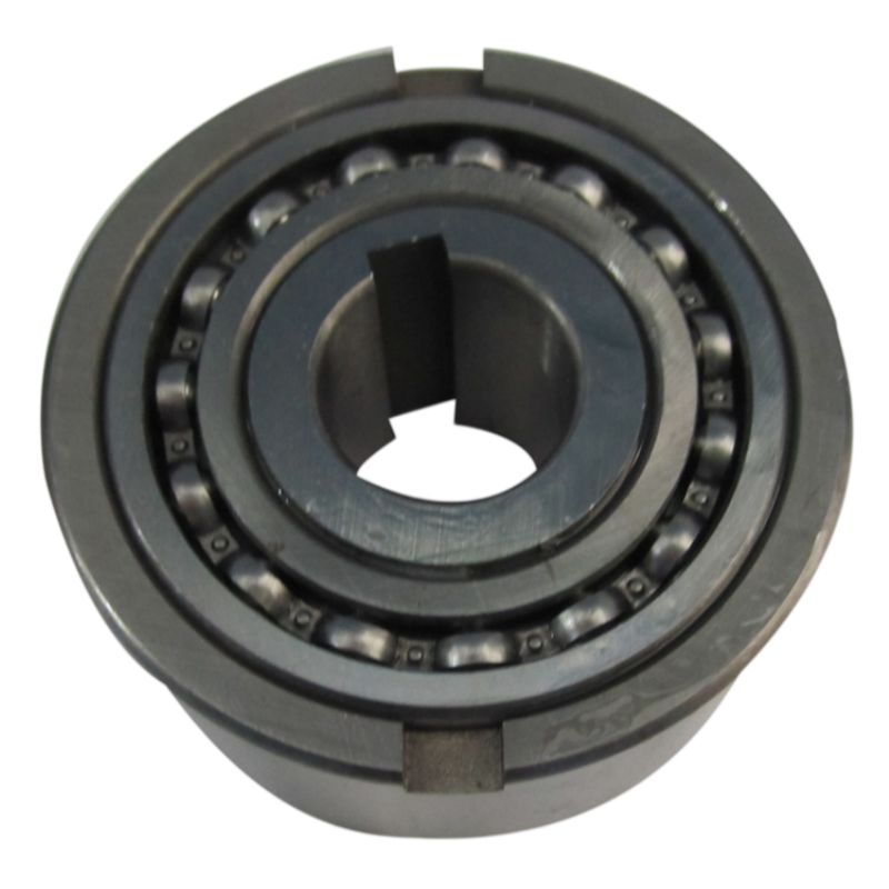
In high-torque industrial transmissions, pure rolling support must often interface directly with directional overrun mechanisms. This is where specialized mechanical clutch assemblies integrate precision bearing geometries with internal locking elements:
- Radial and Thrust Support: Flanged bearing units absorb simultaneous radial loads ($F_r$) and bidirectional axial loads ($F_a$), transferring locating forces directly into the frame structure without external retaining hardware.
- Torque Decoupling & Anti-Reverse Action: Precision sprag or cam clutch assemblies—such as the CSK, ASNU, and flanged FSO series manufactured by LST Sprag Clutch—utilize bearing steel construction to achieve instantaneous lock-up in the overrunning direction while maintaining frictionless freewheeling in the driving direction.
- Elimination of Housing Shoulder Machining: Utilizing a flanged housing interface eliminates the need for internal snap-ring grooves or micro-machined internal bore shoulders, cutting down fabrication cycle times and eliminating micro-deflection points.
2. Technical Comparison: Bearing Geometries and Clutch Series
Different machinery layouts require distinct combinations of free rotation, torque density, and mounting geometry. The table below outlines technical characteristics across standard flanged rolling configurations and heavy-duty overrunning clutch variants.
| Series / Design | Core Mechanical Function | Mounting & Housing Interface | Key Material / Construction | Primary Industrial Suitability |
|---|---|---|---|---|
| Standard Deep Groove Flanged Ball Bearings (F6000 / F6800 / F6900) | Pure radial support with light bidirectional axial locating | External solid flange on outer ring; slip or press fit | GCr15 bearing steel / AISI 52100; pressed steel cage | High-speed instrumentation, small gearboxes, textile spindles |
| CSK / CSK..PP Series (Bearing-Supported Clutch) | Integrated radial bearing with sprag one-way clutch | Keyway on inner/outer race (PP) or interference press-fit | Hardened bearing steel races; precision formed sprags | Packaging machines, exercise equipment, agricultural drives |
| FSO / FSO-HM Series | High-capacity overrunning, backstopping, and indexing | Flanged outer ring with bolt-hole circle for face-mounting | Heavy-duty alloy bearing steel; oil-bath lubricated | Main conveyor drives, heavy gear reducers, elevator backstops |
| ASNU / AV Series | Non-bearing supported roller-type freewheel clutch | Outer race side keyway with external bearing support needed | Case-hardened bearing steel core; sprag/cam elements | Industrial transmissions, dual-motor speed combinations |
| BS / RSBW Series | Low-speed anti-reverse holdback / backstop | Torque arm anchoring on housing; non-flanged bore mount | High-tensile bearing steel; internal roller-ramp profile | Bucket elevators, inclined overland belt conveyors |
For applications demanding complete torque transmission solutions, explore our dedicated one-way clutch for transmission systems engineered with specialized bearing steel components for extended operational life.
3. Engineering Calculations and Quantitative Sizing
Improper sizing of mechanical drive elements leads directly to premature raceway fatigue, sprag slippage, or catastrophic shaft shearing. When configuring drivetrains utilizing flanged ball bearings or cam clutch mechanisms, sizing must incorporate service safety factors and fatigue life calculations.
3.1. Torque Sizing Formula
For backstopping, indexing, and overrunning drives, calculate the required design torque ($T_d$) using nominal drive power and operational shock parameters:
$$T_n = frac{9550 times P}{n}$$
$$T_d = T_n times K_s$$
Where:
- $T_n$ = Nominal mechanical torque in Newton-meters (Nm)
- $P$ = Input power in kilowatts (kW)
- $n$ = Rotational operating speed in revolutions per minute (RPM)
- $K_s$ = Application Service Factor (ranging from 1.5 for uniform electric motor loads to 2.5 – 3.5 for reciprocating engines, bucket elevators, and heavy shock crushers)
3.2. Bearing Rating Life (ISO 281)
The standard nominal L10 fatigue life for the bearing rolling elements within the drivetrain is calculated as:
$$L_{10} = left( frac{C}{P_r} right)^p times frac{10^6}{60 times n}$$
Where:
- $L_{10}$ = Nominal bearing life in operating hours ($90%$ reliability threshold)
- $C$ = Basic dynamic load rating in Newtons (N)
- $P_r$ = Dynamic equivalent radial load ($P_r = X cdot F_r + Y cdot F_a$) in Newtons (N)
- $p$ = Exponent of the life equation ($p = 3$ for deep-groove ball bearings, $p = 10/3$ for roller elements)
- $n$ = Rotational speed in RPM
In heavy industrial conveyor pulleys, engineers must verify that the selected dynamic capacity delivers a minimum calculated $L_{10h} ge 60,000$ hours to prevent unpredicted line shutdowns.
4. Operational Parameters and Tolerance Envelopes
Bearing raceways and overrunning assemblies fail rapidly when subjected to shaft deflection, thermal distortion, or out-of-round housing bores. The table below lists critical engineering tolerances and operational constraints for industrial-grade installations.
| Engineering Parameter | Recommended Working Tolerance | Critical Failure Consequence if Breached |
|---|---|---|
| Shaft Runout (TIR) | < 0.025 mm (0.001 in) | Raceway egging, cyclic fatigue, uneven sprag load distribution |
| Housing Bore Tolerance | ISO H7 for standard fit; K7 for light press fit | Outer ring creep, localized stress peaks, bore galling |
| Flange Perpendicularity | Within 0.03 mm relative to shaft axis | Axial pinching, high internal friction, early cage destruction |
| Operating Temperature | -10°C to +80°C (Standard); up to 120°C (Synthetic) | Lubricant breakdown, seal hardening, clutch lock failure |
| Lubricant Selection | ISO VG 32 to 68 (mineral base without EP additives for sprags) | EP additives (graphite, MoS2) induce sprag hydroplaning/slippage |
5. Industrial Applications: Solving High-Risk Transmission Challenges
5.1. Heavy-Duty Belt Conveyors and Bucket Elevators
In inclined bulk handling, sudden power interruptions transform heavy belt loads into uncontrolled reverse acceleration. Utilizing flanged outer-ring clutch units like the FSO or BS series on gearbox secondary shafts provides positive mechanical holdback protection. The robust flange permits direct, rigid bolting to gearbox casings or torque reaction arms, preventing roll-back accidents instantly and safely.
5.2. Speed Reducers and Dual-Motor Drives
Modern thermal power and cement facilities employ auxiliary pony drives alongside main electric motors. One-way assemblies such as the ASNU and MG series decouple the auxiliary motor automatically as soon as the main motor achieves running speed, eliminating high-speed back-driving and preventing catastrophic rotor destruction.
5.3. High-Precision Packaging and Textile Machinery
Intermittent paper indexing and yarn feed systems rely on the CSK and HF/HFL drawn cup series. By pairing deep groove bearing tracks with instant needle-roller or sprag wedge actions, machines achieve indexing frequencies up to 1,200 cycles per minute with zero backlash and minimal positional drift.
6. Total Cost of Ownership (TCO): Initial Capital vs. Lifecycle Operational Risk
Procurement teams frequently default to evaluating bearings and transmission clutches strictly on initial purchase price (Capex). However, in high-output processing plants, direct acquisition costs account for less than 8% of total lifecycle expenditure.
| Lifecycle Element | Budget / Commodity Component | LST Sprag Clutch Industrial Spec | TCO Financial Impact |
|---|---|---|---|
| Initial Procurement (Capex) | Baseline unit price ($) | Comparable factory-direct pricing ($$) | Minimal variance over 5-year accounting cycles |
| Installation & Fitment | Requires shims, snap rings, bore machining | Standard flanged bolt circles; self-locating | Reduces setup and alignment labor by 40% |
| Mean Time Between Failures (MTBF) | 8,000 – 12,000 hours (inconsistent hardening) | 40,000+ hours (pure bearing steel GCr15) | Eliminates 3 planned rebuild cycles per machine |
| Unscheduled Downtime Risk | High risk of sprag slip or raceway spalling | 100% verified torque retention & dynamic test | Prevents catastrophic production outages |
By investing in properly heat-treated bearing steel components and precision-ground flanges, operators eliminate the hidden costs of shaft re-machining, localized fretting corrosion, and unscheduled line stoppages.
7. Regulatory Compliance, Standards, and Structural Safety
Heavy machinery operating across North America, Europe, and Asia-Pacific must comply with strict industrial and workplace safety codes:
- ISO 281 & ISO 76: Defines the calculations for basic dynamic and static load ratings of rolling bearings, ensuring predictable service lifetimes under operating loads.
- DIN 6885: Specifies drive keyway tolerances utilized on key-driven clutch variants (e.g., CSK..P, CSK..PP, ASNU) to eliminate high-stress fretting.
- OSHA 1910.219 (Mechanical Power-Transmission Apparatus): Requires mandatory anti-reverse fail-safes and secure guards on inclined conveyors and bucket elevators to protect plant personnel against reverse drop-back accidents.
- ANSI/AGMA 6013: Standard for industrial gear drives, governing torque amplification, service factors, and bearing fitting practices.
8. Engineering Procurement and Inspection Checklist
Before issuing a purchase order for replacement or OEM flanged bearings and freewheel clutches, technical procurement teams should run through this operational verification checklist:
- Confirm Primary Mode of Operation: Clearly identify whether the application requires continuous overrunning of the inner ring, continuous overrunning of the outer ring, dynamic indexing, or static anti-reverse backstopping.
- Evaluate Combined Loading: Calculate maximum combined radial ($F_r$) and axial ($F_a$) dynamic shock loads. When high torque and radial loads coincide, select integrated bearing-clutch designs such as the CSK, FSO, or pair independent flanged ball bearings with external freewheels.
- Verify Dimensional Specifications: Confirm shaft tolerances (recommended h6/j6 for clutch bores) and housing bore limits (H7/K7) to preserve proper internal clearance.
- Specify Lubrication Regimes: Ensure lubricants do not contain zinc or molybdenum disulphide (MoS2) extreme pressure (EP) additives if sprag elements share oil reservoirs with bearing raceways.
- Audit Supplier Inventory and Delivery Velocity: Confirm that standard models across the AV, ASNU, MG, MZ, FSO, BS, TFS, DC, BWC, RSBW, CSK, HF, and HFL series are maintained in stock. For fast turnaround, standard parts from LST Sprag Clutch feature a one-week lead time, with samples provided (freight collect) for validation. Custom non-standard sizes can also be engineered to match legacy shaft dimensions.
9. Frequently Asked Questions (FAQ)
Can I use standard extreme pressure (EP) grease in a flanged clutch-bearing assembly?
No. Standard EP greases contain chemical friction-reducing additives (such as molybdenum disulphide or graphite) that form slick boundary films on internal components. In overrunning clutches and sprag assemblies, these additives prevent the precision cams or sprags from developing the critical micro-friction lock required for torque transmission, leading to dangerous slip under load. Always specify non-EP mineral oil or certified turbine oils.
What is the primary advantage of a flanged outer ring compared to a standard retaining ring?
A precision-machined solid outer ring flange provides high mechanical rigidity and direct thrust face resistance across the entire housing circumference. Snap rings and circlips concentrate thrust forces into narrow grooves, creating localized stress risers that can deform or sheer under heavy dynamic shock loads or conveyor reversal conditions.
How can I verify whether a backstop clutch is slipping before catastrophic failure occurs?
Monitor operational temperature spikes, listen for high-frequency vibration signatures during freewheel cycles, and perform manual zero-speed backstop engagement tests. If an overrunning assembly rotates backwards beyond specified clearance play during shutdown, internal sprag wear or surface fatigue has occurred, demanding immediate replacement.
What information is required to manufacture custom non-standard clutch sizes?
To produce non-standard or legacy replacement units, provide the exact shaft outer diameter, housing bore diameter, total axial assembly width, desired bolt circle diameter (for flanged designs), maximum continuous overrun speed (RPM), and peak dynamic holding torque (Nm). LST Sprag Clutch engineers custom non-standard dimensions from premium bearing steel with expedited manufacturing turnaround.