When an inclined bulk handling conveyor carrying 1,500 tons per hour experiences an unexpected drive trip or motor power interruption, thousands of tons of material immediately act against gravity. Without an immediate, rigid mechanical lock, the entire loaded belt accelerates backward in a catastrophic runaway backslide. The consequences are severe: destroyed gearboxes, shredded conveyor belts, exploded drive pulleys, catastrophic structural failure, and immediate, life-threatening danger to personnel on the conveyor gallery. While electromechanical motor brakes are standard on modern drive trains, they rely on electrical signals, pneumatic or hydraulic pressure, and friction linings—introducing multiple points of failure. In critical material handling, safety cannot rely on delayed actuation. A mechanical anti-reverse holdback is mandatory.
Selecting the right conveyor backstop clutch manufacturer is an engineering decision that directly impacts operational safety, asset integrity, and Mean Time Between Failures (MTBF). This technical guide provides plant managers, mechanical drive designers, operations directors, and procurement specialists with an engineering-level breakdown of mechanical backstop clutches: working principles, metallurgical requirements, mathematical sizing formulas, mounting topologies, regulatory frameworks, and Total Cost of Ownership (TCO) benchmarks.
1. Mechanical Working Principles of Conveyor Backstops
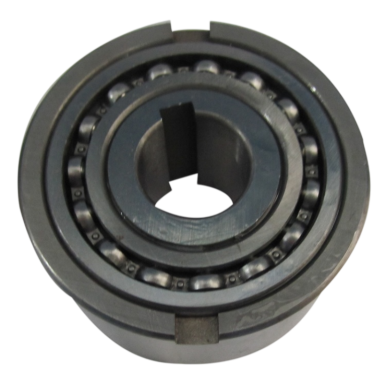
A conveyor backstop—also designated in bulk material handling as an anti-reverse clutch, one-way holdback, or freewheeling sprag clutch—is a purely mechanical directional control element. Its operation is governed by kinematic geometry rather than external control logic, sensors, or power sources.
Overrunning vs. Instant Mechanical Locking
During normal conveyor operation, the backstop operates in freewheeling (overrunning) mode. The inner race, keyed directly to the drive shaft, rotates freely in the drive direction while the outer race remains stationary, anchored to the machine framework via a torque arm or rigid flange. A fluid hydrodynamic or elastohydrodynamic lubricant film separates the internal rolling or cam elements from the raceways, minimizing friction and parasitic drag.
The instant forward shaft rotation drops to zero—at the threshold of reverse gravitational roll—the internal locking elements (cams, sprags, or precision rollers) wedge instantaneously between the cylindrical inner and outer raceways. This mechanical engagement produces rigid, zero-backlash holding torque. The reverse gravitational force of the loaded belt is immediately redirected through the backstop housing and torque arm directly into the conveyor foundation structure, preventing reverse rotation before dynamic reverse velocity can develop.
Internal Geometries: Sprag, Roller-Ramp, and Cam Clutches
Industrial backstops utilize distinct mechanical architectures depending on torque requirements, shaft speeds, and mounting locations:
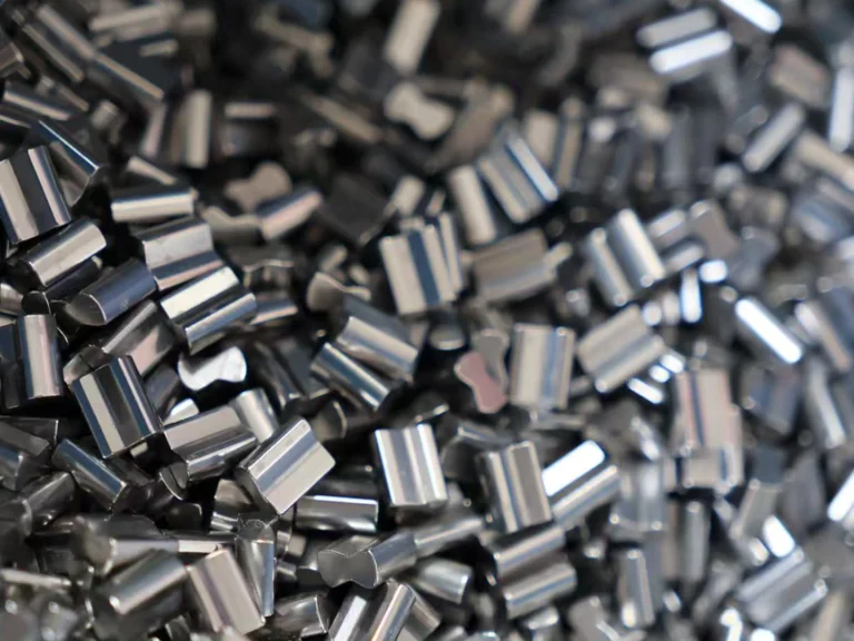
- Sprag Type: Uses precision-profiled, figure-eight or asymmetrical cam sprags retained by garter springs within an annular space. Sprags pivot slightly during forward rotation to clear the raceway or glide with minimal contact, then cam over instantaneously under reverse bias. Sprag clutches provide the highest torque density per unit volume because a high population of sprags shares the torsional load evenly.
- Roller-Ramp Type: Utilizes precision-machined cylindrical rollers positioned on inclined internal ramp flats. Springs push the rollers toward the narrow end of the ramp. During forward rotation, the rollers move back against the springs to freewheel. Upon reverse rotation, the rollers wedge instantly between the flat ramp and the outer circular race. Roller-ramp clutches are highly durable in moderate-to-low-speed regimes and tolerant of severe shock loads.
- Centrifugal Lift-Off Sprag Clutches: Designed for high-speed continuous overrunning. When the inner race reaches a designated “lift-off” rotational speed, centrifugal forces act on the center of gravity of the sprags, overcoming spring tension and swinging them entirely out of physical contact with the outer race. This eliminates metal-to-metal contact during continuous operation, dropping frictional wear and heat generation to zero.
2. Metallurgical Standards & Structural Architecture
The reliability of a conveyor backstop is rooted in its metallurgy. Under reverse loading, the contact zone between a sprag or roller and the bearing raceway experiences extreme Hertzian contact stress, often exceeding 2,500 to 3,000 MPa. Substandard materials suffer immediate subsurface fatigue cracking, case crushing, and brinelling, leading to catastrophic slip.
At LST Sprag Clutch, all critical load-bearing components—inner raceways, outer housings, sprags, and rollers—are manufactured exclusively from premium-grade bearing steel (such as GCr15 / AISI 52100 high-carbon chromium steel or 20CrNiMo / AISI 8620 carburizing alloy steel). Precision manufacturing processes ensure critical operational performance:
- Deep Case Hardening & Martensitic Heat Treatment: Load surfaces are heat-treated to an ultra-hard surface rating of HRC 60–64 to resist abrasive wear, while retaining a core toughness of HRC 32–40 to absorb extreme torsional shock loads without brittle fracture.
- Precision Ground Raceways: Super-finished raceway surfaces control surface roughness down to $Ra le 0.2,mutext{m}$, ensuring uniform contact lines, optimal elastohydrodynamic oil film maintenance, and zero stress concentration hot spots.
- Heavy-Duty Sealing Systems: Bulk handling environments in mining and cement plants are heavily contaminated with abrasive dust and moisture. Industrial backstop assemblies utilize labyrinth seals, multi-lip Viton/NBR contact seals, and external grease purges to prevent particle ingress that could jam internal springs and sprag cages.
3. Comprehensive Series Breakdown: LST Sprag Clutch Portfolio
LST Sprag Clutch manufactures and stocks a complete engineering spectrum of overrunning clutches, holdbacks, and cam clutches. For conveyor and bulk material handling systems, matching the series precisely to drive train placement and torque profile is critical.
| Series | Internal Architecture | Mounting Topology | Primary Industrial Applications | Key Operational Advantage |
|---|---|---|---|---|
| BS Series | Cam / Sprag with Torque Arm | Low-speed shaft (direct pulley mount) | Inclined belt conveyors, bucket elevators | Direct shaft locking; bypasses gearbox failure risk; high static torque capacity |
| FSO Series | Sprag Clutch with Flange | Shaft-to-pulley / shaft-to-gear flange | Gearbox intermediate shafts, dual-drive systems | High overrunning speeds; oil-bath lubricated; versatile flange connections |
| MG / MZ Series | Precision Sprag | Shaft keyway mount / End-cover mount | General reducers, packaging lines, conveyors | Compact footprint; standard bearing dimensions; exceptional torque-to-weight ratio |
| ASNU Series | Roller-Ramp Type | Press-fit inner / Keyed outer race | Bucket elevators, textile drives, feeding units | Non-bearing supported roller ramp; handles high shock loads and intermittent overrunning |
| AV Series | Roller Type with Centering Bearings | Integrated bearing mount | Agricultural machinery, light inclined handling | Integral plain or ball bearings; simplifies mechanical shaft support design |
| TFS / DC Series | Sprag Cage Assembly | Direct integration into OEM gearbox castings | Compact drive reducers, mobile mining equipment | Cageless or minimalist envelope; allows direct raceway integration on machine shafts |
| BWC / RSBW Series | Cam / Sprag One-Way Assembly | Low-speed shaft with torque bracket | Mine conveyors, cement bucket elevators | Rugged external torque arm dampens shock loads through elastomeric end cushions |
| CSK / HF / HFL | Drawn Cup / One-Way Bearing | Standard metric bearing envelope | Automation, lightweight packaging conveyors | Economical, compact; combines radial support and anti-reverse locking |
For large-tonnage bulk material handling, the BS Series Backstop Clutch serves as the primary industry standard. Mounted directly on the extended head pulley shaft, it incorporates an integral torque arm that transmits reaction loads to the concrete or steel foundation. This layout guarantees that if an upstream gearbox shaft shears, a coupling fails, or the primary drive chain snaps, the backstop holds the conveyor securely in place.
4. Technical Sizing & Torque Calculation Methodology
Undersizing a backstop clutch is one of the most dangerous design errors in bulk material handling. Backstop sizing must never be based strictly on motor nameplate horsepower. Instead, sizing must account for peak gravitational stall torque, loaded belt profiles, system efficiency losses, and high-inertia dynamic shock loads.
Standard Engineering Formulas
According to the Conveyor Equipment Manufacturers Association (CEMA), the mechanical torque required to hold a loaded inclined conveyor at rest is derived from the lift torque minus conveyor frictional resistance, multiplied by an engineered Service Factor ($SF$):
CEMA Static Holdback Torque Calculation:
T_static = ((M_material + M_belt_inclined) × g × sin(θ) × (D_pulley / 2)) – (F_friction × (D_pulley / 2))
Where:
- M_material = Total mass of loaded bulk material on the inclined section (kg)
- M_belt_inclined = Total mass of the moving belt carcass along the incline (kg)
- g = Gravitational acceleration (9.81 m/s²)
- θ = Angle of inclination (degrees)
- D_pulley = Pitch diameter of the drive/head pulley (m)
- F_friction = System frictional resistance force working in the direction of backstop hold (N)
Safety Rule: In engineering practice, many safety-critical designs assume F_friction = 0 to evaluate the worst-case scenario (such as rain or belt lubrication reducing friction), ensuring the backstop handles total unimpeded gravitational potential.
Motor Stall Torque & Drive Reducer Conversion
When selecting a backstop installed on an intermediate reducer shaft or high-speed motor shaft, torque must be calculated using drive motor breakdown torque and gear reduction ratio ($i$):
T_backstop = (P_motor × 9550 / N_shaft) × SF
Where:
- P_motor = Electric motor nominal power (kW)
- N_shaft = Rotational speed of the shaft where the backstop is positioned (RPM)
- SF = Service Factor (typically 1.5 to 2.5 for uniform material; 2.5 to 3.5 for bucket elevators and severe cyclic shock loading in mining).
Worked Example: Sizing a BS Series Low-Speed Shaft Backstop
Consider an inclined mine conveyor with the following parameters:
- Drive Pulley Diameter: 1,000 mm (0.5 m radius)
- Total Material Load on Incline: 45,000 kg
- Angle of Incline: 14° (sin(14°) ≈ 0.2419)
- Conveyor Efficiency / Retarding Friction: Conservative safety estimate ignored ($F_{friction} = 0$)
- Specified CEMA Service Factor: 2.0
Step 1: Calculate the gravitational tangential rollback force:
F_rollback = 45,000 kg × 9.81 m/s² × 0.2419 = 106,788.75 N
Step 2: Calculate nominal holding torque at the head shaft:
T_nominal = 106,788.75 N × 0.5 m = 53,394.38 N·m
Step 3: Apply the required Industrial Service Factor ($SF = 2.0$):
T_selection = 53,394.38 N·m × 2.0 = 106,789 N·m
Based on this calculation, the plant engineer would select a heavy-duty LST BS-Series Backstop with a minimum static holding torque rating of 110,000 N·m to ensure complete structural safety margins under full stall load conditions.
5. Installation Topologies: Low-Speed Shaft vs. High-Speed Shaft
The mechanical location of the backstop clutch within the drive train dramatically impacts safety, component cost, and system reliability.
| Selection Parameter | Low-Speed Shaft (Head Pulley Mount) | High-Speed Shaft (Motor/Reducer Input) | Intermediate Shaft (Gearbox Integral) |
|---|---|---|---|
| Torque Requirement | Extremely High (Full load torque) | Low (Torque divided by gear ratio $i$) | Moderate |
| Physical Clutch Size | Large footprint, heavy torque arm | Compact, lightweight assembly | Medium envelope |
| Gearbox Failure Protection | 100% Protection: Holds load even if gearbox, couplings, or gears break completely | Zero Protection: If gearbox shears or coupling breaks, load slides back uncontrolled | Partial Protection: Dependent on final stage bull gear integrity |
| Initial Capital Cost | Higher initial investment | Lower initial investment | Moderate capital cost |
| Mechanical Wear | Minimal; shaft rotates at very low RPM (e.g., 20–60 RPM) | Higher; continuous overrunning at 1200–1800 RPM requires lift-off sprags | Moderate overrunning speeds (150–400 RPM) |
| Recommended Applications | Heavy mining, overland conveyors, high-capacity bucket elevators | Small, low-risk packaging, auxiliary drives | Standard industrial reducers, medium bulk handling |
In high-tonnage mining and infrastructure conveyors, low-speed shaft mounting using the BS or RSBW Series is universally recognized as the safest design. Placing the backstop directly on the head pulley shaft eliminates any reliance on upstream gear teeth, intermediate shafts, or low-speed flexible couplings.
6. Total Cost of Ownership (TCO) & Reliability Analysis
Procurement teams are often tempted by low-cost, generic backstops. However, an analysis of Total Cost of Ownership (TCO) reveals that the initial purchase price of a backstop represents less than 3% of its operational life cost.
Financial Risk Breakdown: Component Cost vs. Unscheduled Outage
Consider an average coal, copper, or aggregate mine:
- Capex (Premium Backstop): Direct factory-supplied LST bearing steel backstop: $3,500 – $8,000
- Capex (Low-grade Generic Clutch): $1,800 – $4,500 (Initial apparent savings: ~$2,500)
- Downside Risk (Internal Component Failure):
- Unscheduled emergency plant downtime: $8,000 – $25,000 per hour
- Structural repair from belt rollback (shredded belt, damaged idlers, clean-up labor): $60,000 – $250,000
- Regulatory fines (OSHA/MSHA safety violations): $15,000 – $75,000+
A single backstop slip or failure can quickly surpass $150,000 in direct losses. Investing in precision-engineered bearing steel components with verified heat treatments produces an immediate, substantial return on investment by mitigating operational risk.
Operational Lead Times & Supply Chain Agility
In MRO (Maintenance, Repair, and Operations) and OEM assembly environments, delivery delays stall commissioning schedules. Traditional industrial distributors often quote 8 to 16 weeks for industrial backstops. LST Sprag Clutch maintains a standard inventory program for high-demand configurations across the AV, ASNU, MG, MZ, FSO, BS, TFS, DC, BWC, and RSBW series, enabling a standard one-week lead time on stock units. For engineering validation, functional samples are readily supplied with freight collect, shortening machine design cycles.
7. Regulatory Compliance, Safety Codes, and Quality Standards
Industrial conveyor systems are subject to strict regulatory oversight to prevent workplace hazards. Installing certified, properly engineered backstops is a regulatory requirement across major jurisdictions:
- OSHA 29 CFR 1926.555 & 1910.218: Mandates that all inclined conveyors, where reverse motion presents a danger to personnel, must be equipped with mechanical anti-runaway devices or continuous backstops that act automatically upon drive power interruption.
- MSHA 30 CFR § 56.9201 & § 57.9201 (Mine Safety & Health Administration): Explicitly requires inclined conveyors in surface and underground mining operations to be equipped with dependable holdbacks to prevent rollbacks during emergency stops or power interruptions.
- CEMA Safety Standard 575: Outlines stringent sizing ratios, thermal limits, and mechanical design factors for backstops used in bulk material handling.
- ISO 9001:2015 Manufacturing Standards: Dictates rigorous non-destructive testing (NDT), dimensional coordinate checks, and metallurgical case-depth validation on bearing steel components.
8. Engineering Procurement Checklist
Before issuing a Purchase Order for replacement or new-build conveyor holdback assemblies, ensure your technical procurement and mechanical engineering teams evaluate the following ten criteria:
- Torque Verification: Has the selection torque factored in dynamic shock loads using a CEMA-compliant Service Factor (SF ≥ 1.5 for steady conveyors, SF ≥ 2.5 for bucket elevators)?
- Shaft Fit & Keyway Standards: Are bore dimensions and keyway tolerances machined to standard ANSI B17.1, DIN 6885/1, or specific custom tolerances to prevent shaft fretting?
- Operating Speed Range: Does the nominal shaft RPM stay safely within the maximum overrunning speed limits of the specified sprag or roller assembly?
- Thermal Dissipation: In continuous overrunning conditions, does the unit maintain thermal equilibrium below the lubricant breakdown point (maximum oil temperature ≤ 80°C / 176°F)?
- Lubrication Architecture: Is the clutch configured for oil-bath lubrication with sight level indicators, or synthetic high-performance EP grease suitable for ambient operating temperatures?
- Torque Arm Configuration: Is the torque arm designed with freedom for axial movement to prevent destructive side-loading on the internal supporting bearings?
- Environmental Protection: Are non-contact labyrinth or Viton lip seals installed to seal out abrasive cement, silica, coal, or agricultural particulate?
- Material Certification: Can the manufacturer verify the use of high-carbon alloy bearing steel (e.g., GCr15 / 52100) with surface case hardness exceeding HRC 60?
- Customization Availability: If your machine envelope features a non-standard bore diameter, special keyways, or specific flange patterns, can the factory provide rapid engineering modifications?
- Lead Time & Spare Parts: Does the manufacturer guarantee fast dispatch (one-week standard delivery) to support emergency maintenance turnarounds?
9. Maintenance & Lubrication Protocol
Even the highest-grade bearing steel backstop will suffer premature failure if operated without proper lubrication protocols. Friction during overrunning generates internal heat that must be safely dissipated.
Oil vs. Grease Selection Criteria
Oil-Bath Lubrication: Preferred for medium-to-high-speed horizontal shaft applications (e.g., FSO, MG Series). Use high-quality non-EP (Extreme Pressure) circulating turbine or hydraulic oils (ISO VG 32 to ISO VG 68). Warning: Oils containing high concentrations of friction-modifying EP additives or graphite/molybdenum disulfide solids must never be used in sprag or roller-ramp clutches. These additives coat the raceways, decreasing the micro-friction required for sprags to bite, which can induce catastrophic mechanical slippage under load.
Grease Lubrication: Typically utilized on low-speed vertical bucket elevator drives and enclosed BS-series backstops equipped with specialized seals. Use synthetic, low-shear-thinning lithium complex greases rated for the specific ambient operating range (-40°C to +50°C).
Inspection Schedule
- Initial 100 Hours: Check oil level, check torque arm anchor pins for correct clearance, and monitor running temperature during maximum belt load.
- Monthly: Visually inspect oil sight glasses for contamination, emulsification, or level drops. Check torque arm elastomeric buffers for aging or excessive deflection.
- Every 2,000 Hours (or 6 Months): Conduct full oil change. Clean magnetic drain plugs to inspect for metallic wear particles indicating early fatigue spalling.
10. Frequently Asked Questions (FAQ)
What is the difference between a backstop clutch and an electromechanical shoe/disc brake?
An electromechanical brake relies on external power removal, electrical actuation, solenoid response times, and friction friction pads. It inherently exhibits a small time delay (150–400 milliseconds) before full clamping torque is achieved. During this delay, an inclined conveyor can rapidly gather reverse momentum, causing dynamic shock loads that can snap drive chains or shear reducer shafts when the friction pads finally bite. In contrast, an industrial backstop clutch is a direct-acting mechanical component. It operates purely on rotational kinematics with zero clearance, locking instantly at the microsecond rotation transitions to reverse, preventing any reverse acceleration from developing.
What are centrifugal lift-off sprags, and when are they required?
Centrifugal lift-off sprags are engineered with an off-center pivot mass. When the rotating inner shaft reaches a designated angular velocity (known as lift-off speed), centrifugal force overcomes the holding garter spring tension, causing the sprags to lift away from the outer raceway. This eliminates contact friction, eliminating heat generation and mechanical wear during overrunning. Lift-off backstops are essential in continuous, high-speed applications—such as dual-motor conveyor drives, auxiliary drives, or drives operating above 900 RPM.
Can LST provide custom bore sizes, keyways, and special torque arm configurations?
Yes. While LST Sprag Clutch carries broad inventories of standard metric and imperial bore sizes across the AV, ASNU, MG, MZ, FSO, BS, TFS, DC, BWC, RSBW, CSK, HF, and HFL series, we routinely engineer and machine custom non-standard bores, splines, special keyway offsets, and customized torque arms tailored to fit existing plant footprints during retrofits. Direct factory engineers assist you throughout the specification process.
What is the typical delivery timeline for standard vs. customized non-standard series?
Standard catalog models are stocked in inventory and carry a typical one-week lead time for order processing and dispatch to the US market. Custom-machined units, non-standard bore configurations, or specialized mounting flanges are produced with industry-leading production turnaround. Samples for OEM prototyping and engineering validation can be provided promptly upon request (shipped freight collect).
Conclusion: Securing Plant Operations with LST Engineering
Uncontrolled conveyor rollback poses an unacceptable operational and financial risk in modern industrial plants. Specifying precision-engineered backstop clutches manufactured from through-hardened, high-grade bearing steel eliminates unpredictable drive failures, ensures workplace safety compliance, and protects expensive upstream mechanical drives from catastrophic destruction.
Whether you are designing a high-capacity mining conveyor system, upgrading aging bucket elevator drives, or maintaining plant equipment across the United States, partner with a dedicated manufacturer. Contact LST Sprag Clutch today to speak directly with an application engineer, request technical datasheets, order testing samples, or receive a fast quotation on standard or custom anti-reverse solutions.