In bulk material handling, heavy mining, and continuous process manufacturing, an unconstrained mechanical reversal is among the most destructive events a powertrain can experience. When an inclined conveyor handling thousands of tons of ore per hour or a heavily loaded vertical bucket elevator experiences a sudden motor trip or grid failure, gravity immediately attempts to accelerate the material backward. Without instantaneous mechanical intervention, this uncontrolled reverse acceleration leads to catastrophic gear train implosion, projectile debris, pulverized conveyor splices, and immense safety risks to facility personnel. Selecting an experienced, technically verified industrial backstop clutch supplier is not merely a component purchasing decision; it is an engineered safeguard protecting millions of dollars in capital equipment and preventing prolonged operational downtime.
At LST Sprag Clutch, we engineer and supply high-precision overrunning clutches, mechanical holdbacks, and anti-reverse freewheel components built to withstand extreme mechanical shock loads. Manufactured from premium, vacuum-degassed bearing steel, our backstop assemblies deliver instant zero-backlash locking, exceptionally low overrunning drag, and dependable torsional rigidity. Whether you are integrating a high-speed backstop into an industrial gear reducer or mounting an ultra-high-torque holdback directly to a conveyor head pulley, this guide provides the kinematic principles, quantitative sizing methodologies, and procurement evaluation criteria required by plant managers, design engineers, and industrial distributors.
Kinematic Fundamentals: How Industrial Backstops Execute Zero-Backlash Locking
A backstop clutch—often referred to in transmission engineering as an anti-reverse freewheel, one-way clutch, or holdback—is a directional mechanical device designed to permit free rotation in the drive direction while preventing reverse rotation virtually instantaneously. Unlike friction-based dynamic brakes or solenoid-operated electromechanical holdbacks, mechanical backstops operate purely on hydrodynamic and mechanical contact principles, requiring no external electrical power, sensors, or automated actuation to engage.
Sprag vs. Roller-Ramp Kinematic Topologies
Industrial backstops generally rely on one of two fundamental contact geometries: sprag elements or ramp-and-roller mechanisms. Understanding the mechanical behavior of these internal elements is critical when selecting an industrial backstop clutch supplier for specific RPM and torque profiles.
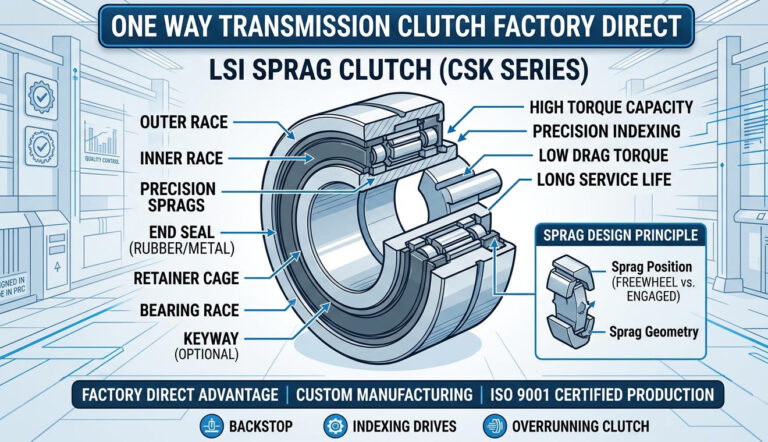
- Sprag Element Geometry: A sprag clutch utilizes non-cylindrical, cam-profiled wedging elements positioned between concentric cylindrical inner and outer races. During forward overrunning, the hydrodynamic oil wedge and the asymmetrical geometry of the sprag allow the inner or outer race to rotate freely with minimal frictional drag. When rotational direction attempts to invert, the sprags pivot instantly, jamming between the races via a precision-calculated cam engagement angle. The compressive force increases proportionally with the applied reverse torque, creating an unyielding, rigid mechanical lockup without perceptible backlash.
- Ramp-and-Roller Architecture: This design incorporates cylindrical rollers set into precision-machined inclined ramps on one race, retained by spring-energized cages against a smooth cylindrical opposing race. Overrunning pushes the rollers down the ramps against spring compression, allowing fluid rotation. Upon reversal, the springs drive the rollers up the inclined ramps, wedging them firmly between the races. Roller-ramp systems exhibit exceptional durability in low-to-medium speed regimes and high-viscosity lubrication environments.
Hydrodynamic Lift-Off and Wear Reduction
In high-speed continuous overrunning applications—such as backstops installed on the intermediate or input shafts of planetary and helical gear reducers—continuous mechanical rubbing between the sprags and races would cause parasitic frictional heat and premature surface fatigue. To eliminate this issue, premium series engineered by LST Sprag Clutch utilize aerodynamic and hydrodynamic lift-off designs (often referred to as “contactless overrunning”).
At operational overrunning speeds, centrifugal forces acting upon the carefully balanced sprag mass overcome the tension of the garter springs. The sprags lift off the raceway by a few microns, riding on a microscopic hydrodynamic lubricant barrier. This completely eliminates metal-to-metal contact during continuous operation, driving mechanical friction virtually to zero, minimizing operating temperatures, and extending the service life of internal raceways indefinitely under normal continuous operation.
The LST Sprag Clutch Product Architecture
Industrial powertrain designs require varied physical geometries, mounting provisions, and torque capabilities. LST Sprag Clutch supplies a comprehensive spectrum of standard, modular, and specialized one-way clutches engineered to meet diverse OEM specifications and plant retrofits. Explore our specialized one-way clutches for transmission systems to evaluate dimensional drawings and interface options.
| Series | Internal Mechanism | Key Mechanical Features | Typical Shaft Location | Primary Industrial Applications |
|---|---|---|---|---|
| BS Series | Cam / Sprag with Torque Arm | Self-contained, heavy-duty casing, integrated torque arm to absorb reaction forces without internal bending moments. | Low-speed Head Pulley Shaft | Inclined belt conveyors, bucket elevators, bulk terminal handling. |
| FSO Series | Precision Sprag | Flange-mounted outer race, oil-lubricated with double lip seals, high overrunning speed capacity. | Gearbox Intermediate Shaft | Helical gearboxes, dual-drive systems, fan drives, industrial pumps. |
| MG / MZ Series | Sprag Elements | Standard metric bearing dimensions, keyway connection on inner race, high torque density per radial footprint. | Internal Reducer Shaft | General machinery power transmission, packaging machines, industrial reducers. |
| ASNU Series | Roller-Ramp | Non-bearing supported; outer race features side notches for axial housing keying; elastic dynamic absorption. | Internal Machine Frame | Textile processing, converting lines, indexers, light bucket elevators. |
| AV Series | Roller-Ramp with Bearings | Built-in plain bearings for radial load support; robust end covers with dynamic sealing. | Overhung Shaft Drives | Agricultural machinery, medium conveyor drives, mining auxiliary drives. |
| CSK / CSK..PP | Sprag (Bearing Style) | Dimensions identical to 6200 series deep-groove ball bearings; available with single or double keyways. | Direct Electric Motor Shaft | Light industrial automation, small gear reducers, textile feeders. |
| TFS / DC / BWC | Sprag Cages / Elements | Retainer assemblies without inner/outer races; designed for direct customer-hardened shaft and housing integration. | Integrated OEM Powertrains | Automotive transmissions, precision reducers, high-volume machinery OEMs. |
| RSBW Series | Roller-Ramp Low Speed | External torque arm, robust open-frame design engineered for dirty, high-particulate bulk material environments. | Head Shaft / Tail Shaft | Quarry conveyors, stone crushers, mining transshipment hubs. |
| HF / HFL Series | Needle Roller One-Way | Drawn cup needle roller clutches; compact radial envelope; rapid engagement response. | Precision Sub-Assemblies | Printing machinery, office equipment, light packaging indexing. |
Quantitative Sizing: Mechanical Engineering Formulas for Backstop Selection
Undersizing an industrial backstop can result in explosive mechanical yield when dynamic reversal shocks hit the drive train. Conversely, excessive oversizing introduces severe parasitic rotational inertia and needless capital expenditure. Reliable engineering teams employ systematic mechanical calculations to establish static holding requirements, dynamic shock derating, and thermal dissipation thresholds.
1. Nominal Static Holdback Torque Calculation
For inclined material conveying systems, the basic nominal backstop torque ($T_N$) generated by gravity under fully loaded conditions must be calculated from physical conveyor parameters:
TN = [ (Mm × sin(θ) ± Mb × sin(θ) − Ff) × (Dp / 2) ] × η
Where:
- Mm: Total mass of conveyed bulk material along the inclined length (kg).
- Mb: Mass of the moving conveyor belt structure (kg).
- θ: Angle of conveyor inclination (degrees).
- Ff: Frictional resistance of idlers, pulleys, and material skirtings opposing backward movement (N).
- Dp: Pitch diameter of the primary driving head pulley (m).
- η: Powertrain mechanical efficiency between backstop mounting location and the head pulley (η = 1.0 if direct-mounted to head shaft; η ≈ 0.92–0.96 per gear reduction stage if mounted within or behind a reducer).
2. Dynamic Sizing and Service Factor Application
Nominal static torque does not represent real-world stopping forces. When a drive motor trips, dynamic load spikes occur as conveyor belt elasticity stretches and snaps back, or as materials shift dynamically within elevator buckets. Therefore, the required minimum design torque ($T_{design}$) must incorporate an engineering service factor ($S_f$):
Tdesign = TN × Sf
Standard engineering practices outlined by the Conveyor Equipment Manufacturers Association (CEMA) and the American Gear Manufacturers Association (AGMA) dictate the following minimum service factor guidelines:
- Uniform, non-regenerative drives: $S_f = 1.5$ to $1.75$
- Heavy bulk handling, steep inclination, high elasticity belt: $S_f = 2.0$ to $2.5$
- Multiple drives with potential non-synchronous load distribution: $S_f = 3.0$
3. Reducer Input vs. Head Shaft Torque Transformation
If the backstop is integrated into the high-speed shaft or intermediate shaft of a gear reducer rather than directly on the head pulley shaft, the torque requirement decreases proportionally to the reduction ratio ($i$), while overrunning rotational speed ($n$) increases by the same ratio:
Tshaft = Thead / (i × η) | nshaft = nhead × i
Engineers must cross-verify that the chosen backstop’s maximum permissible overrunning speed ($n_{max}$) exceeds $n_{shaft}$ by at least 15% to 20% across all operating frequency inverter ranges.
Mounting Architecture: High-Speed Intermediate Shaft vs. Low-Speed Head Shaft
One of the most consequential decisions plant managers and machinery designers face is choosing the installation location within the kinematic train. Mounting the backstop within the reducer versus on the head pulley shaft involves deep trade-offs in torque demand, mechanical component risk, and total installed cost.
| Engineering Parameter | High-Speed Shaft Mounting (Internal Reducer) | Low-Speed Shaft Mounting (Direct Head Pulley) |
|---|---|---|
| Torque Requirement | Significantly lower (divided by total gear ratio $i$). Allows compact series like FSO, MG, or ASNU. | Extremely high. Requires heavy-duty backstops with external torque arms (BS, RSBW Series). |
| Physical Footprint & Weight | Compact, lightweight, integrated within gearbox casing or bell housing. | Large physical diameter, heavy structural support required for torque arm anchoring. |
| Single Point of Failure Risk | High Risk: If any gear, tooth, shaft, or coupling between the backstop and the head pulley breaks, the backstop cannot prevent conveyor rollback. | Zero Transmission Risk: Directly coupled to the pulley shaft. Prevents backslide regardless of upstream drive or gearbox failure. |
| Overrunning Heat Generation | Continuous high-speed rotation generates more friction and heat; requires hydrodynamic lift-off sprags or circulating oil cooling. | Low RPM overrunning; thermal generation is minimal. Simple grease or sealed oil lubrication is sufficient. |
| Initial Equipment Cost (Capex) | Substantially lower unit purchase cost due to smaller physical size and lower torque rating. | Higher initial component cost due to massive torque requirement and bearing steel mass. |
Industrial Applications & Field Duty Profiles
Every industrial sector imposes distinct operational stresses, particulate exposures, and cycle demands on backstop hardware. LST Sprag Clutch provides specialized design modifications to meet the strict realities of these operating environments.
1. Heavy Mining and Quarry Inclined Conveyors
Conveyors carrying coal, copper ore, iron pellets, and crushed aggregate operate continuously under abrasive particulate loads. In this domain, the BS Series and RSBW Series dominate. Their integrated torque arms are bolted to the machine frame using dynamic reaction dampeners. These holdbacks isolate the gearbox completely: should a primary gear tooth strip under transient shock, the low-speed BS unit holds the entire gravity-loaded belt rigid, averting disastrous spillages and structural collapse.
2. Vertical Bucket Elevators
Bucket elevators present zero room for belt or chain elasticity buffering. Reversal immediately causes bottom boot jamming, bucket shearing, and violent chain snapping. Reducer-mounted FSO and MG series backstops provide instantaneous lockup without dynamic recoil. For continuous-run grain terminals, mining bucket systems, and cement calcination towers, instantaneous locking precision prevents reverse acceleration before it can build destructive kinetic energy.
3. Reducers, Turbomachinery, Fans, and Centrifugal Pumps
When multiple high-volume pumps or industrial ventilation fans discharge into a common manifold, shutting off one unit can induce violent reverse windmilling caused by backpressure from operating units. Reverse rotation during motor startup can draw catastrophic locked-rotor amperage, tripping switchgear or burning out stator windings. Integrating internal ASNU, MZ, or CSK freewheels into motor or reducer drivetrains ensures that drive shafts remain strictly stationary during standby, facilitating seamless on-the-fly restarts.
Material Science, Precision Manufacturing, and Metallurgical Controls
The structural integrity of a backstop clutch is governed entirely by the metallurgical composition and micro-structure of its contact elements. At LST Sprag Clutch, all primary load-bearing components—including inner races, outer races, sprags, and rollers—are machined from certified, high-grade bearing steel (GCr15 / AISI 52100 vacuum-degassed alloy).
- Thermal Core & Case Hardening: Races undergo precision induction or carburizing heat treatments to achieve a surface hardness of HRC 60–64 to an engineered case depth. This ensures extreme resistance to surface contact fatigue (spalling) while maintaining a resilient, shock-absorbing core toughness (HRC 32–40) capable of withstanding dynamic torsional shocks without brittle micro-fracturing.
- Precision Grinding and Superfinishing: Raceways are ground and micro-honed to a surface roughness profile below $Ra le 0.2,mutext{m}$. Eliminating microscopic asperities guarantees uniform hydrodynamic lubricant film distribution, mitigates micro-welding during boundary lubrication phases, and maximizes sprag contact area consistency.
- Garter Spring Longevity: Sprag retaining springs are cold-drawn from premium stainless or high-tensile spring steel alloys, calibrated precisely to maintain exact sprag pitch alignment throughout hundreds of millions of overrunning revolutions without relaxation.
Safety Standards and Regulatory Compliance Frameworks
Industrial machinery installations in the United States and global jurisdictions are strictly governed by mandatory workplace safety codes and design standards. Utilizing unverified, non-traceable backstops introduces severe operational and legal liability.
- OSHA 29 CFR § 1926.555 (Conveyor Safety Regulations): Mandates that all inclined conveyors handling material be equipped with mechanical anti-runaway devices or positive-acting backstops that engage automatically upon power disruption to safeguard personnel working adjacent to conveyors.
- MSHA 30 CFR § 56.14107 & § 56.14109 (Mine Safety and Health Administration): Requires positive mechanical protection against falling, rolling, or sliding conveyor components, particularly on overland aggregate and coal haulage lines.
- AGMA 6013 / 6113 Standards: Specifies design practices and dynamic safety factors for industrial enclosed gear drives, dictating strict service margins when incorporating integrated freewheel holdbacks within reducer gear cases.
Total Cost of Ownership (TCO) & Procurement Strategy
For technical buyers and procurement specialists, evaluating backstop hardware purely on initial purchase price represents a major operational vulnerability. The economic consequences of a single backstop failure dwarf any initial component price variance by orders of magnitude.
| Lifecycle Financial Driver | High-Precision LST Sprag Clutch | Low-Spec Uncertified Clutches | Unmitigated Conveyor Reversal Incident |
|---|---|---|---|
| Initial Acquisition Cost (Capex) | Competitive factory-direct pricing; transparent engineering quotes. | Marginally lower initial purchase invoice (15–25% savings). | N/A |
| Lead Time & Inventory Availability | 1-week lead time on standard stock series; custom rapid tooling. | Uncertain delivery schedules (typically 8–16 weeks with erratic ocean transit). | Unscheduled plant downtime waiting for replacement machinery: $15,000–$100,000+/day. |
| Maintenance & Relubrication Cycle (Opex) | Extended maintenance intervals; high-grade dynamic lip/labyrinth seals prevent lubricant loss. | Frequent teardowns due to premature raceway wear, leakage, and sprag misalignment. | Catastrophic rebuild: complete cleanup, structural realignments, gear replacement. |
| Operational Life Expectancy | 50,000 to 100,000+ continuous overrunning hours under recommended lubrication. | Unpredictable; premature spalling or sprag slippage often observed within 6,000–12,000 hours. | Zero: instant equipment destruction and total write-off. |
Procurement & Technical Evaluation Checklist
Before issuing a purchase order for replacement or OEM backstops, plant engineers and sourcing managers should verify the following parameters:
- Torque Verification: Ensure both continuous overrunning torque and maximum instantaneous holding torque (including dynamic service factor $S_f ge 2.0$) are verified via manufacturer engineering datasheets.
- Bore Tolerance & Keyway Specs: Confirm shaft fit classes (e.g., ISO H7/js6 or imperial class fits) and verify whether keyways conform to DIN 6885 or ANSI B17.1.
- Lubrication Provisions: Determine if the operating envelope demands synthetic ISO VG 220/320 gear oil, low-temp synthetic grease, or specialized non-EP lubricants (extreme pressure additives with friction modifiers can cause sprags to slip during lockup).
- Reaction Force Anchoring: Check that the torque arm mounting allows axial clearance. Torque arms must never be rigidly clamped rigidly in the axial plane; they require clearance to self-align and prevent radial bearing preloading.
- Supplier Responsiveness: Prioritize suppliers maintaining high domestic or regional stock with rapid dispatch capabilities, sample programs for qualification, and custom CNC boring services.
Frequently Asked Questions (FAQ)
What causes an industrial backstop clutch to slip under load?
Backstop slippage is typically caused by three issues: using incorrect lubricants containing slippery extreme-pressure (EP) friction-modifying additives that inhibit mechanical wedging; severe raceway surface fatigue (brinelling or spalling) from excessive cyclic shock loads; or operating below the sprag contact angle threshold due to uncorrected mechanical wear. LST Sprag Clutches mitigate this through precise metallurgical case-hardening and strict lubricant recommendations.
Can LST backstop clutches be retrofitted into existing gearboxes?
Yes. Our MG, MZ, ASNU, and FSO Series are built to international dimensional standards, making them drop-in replacements for standard industrial transmission footprints across major gearbox brands. For non-standard shaft diameters or legacy equipment, custom bore sizing, specialized keyways, and bespoke flange geometries can be precision machined with short lead times.
How does overrunning speed impact backstop selection?
Every backstop series has a strictly calculated maximum overrunning speed ($n_{max}$) determined by the physical diameter of the inner race, sprag mass, and centrifugal force. If an application operates at continuous high RPM, selecting a lift-off sprag design is essential. Exceeding speed limits on standard friction-contact backstops causes rapid frictional heat buildup, seal destruction, and raceway scouring.
What is the typical delivery schedule for replacement backstops?
Standard catalog products—including popular configurations across the BS, FSO, ASNU, MG, AV, and CSK series—are maintained in active warehouse inventory with a standard one-week lead time. For custom engineering designs or non-standard metric/imperial shaft bores, our rapid-turn manufacturing ensures rapid turnaround. Sample units can be dispatched for OEM testing and qualification (freight collect).
Choose LST Sprag Clutch as Your Trusted Industrial Partner
Securing heavy powertrains against catastrophic rotational backslide requires uncompromising engineering precision, traceable bearing-steel metallurgy, and reliable supply chains. LST Sprag Clutch combines deep technical expertise with agile manufacturing and rapid fulfillment to deliver industry-leading anti-reverse solutions to machinery OEMs, gearbox manufacturers, and heavy industrial facilities across the United States and international markets.
Protect your capital assets, eliminate hazardous equipment rollbacks, and minimize unscheduled downtime. Contact our engineering team today to review your dimensional specifications, request technical CAD models, or order prototype samples for validation.